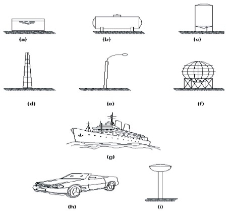
Figure 1. Applications of Cylinder Shells
The thin cylindrical shaped shells undergo weight load failure leading to buckle the shape of shell which leads to the failure of the shell. The buckling failure can be determined by applying practical load analysis on the cylindrical shells. The present paper used three different materials such as Mild steel, Aluminium Alloy and Titanium alloy with the same dimensions such as radius, length and thickness are opted for conducting buckling simulation analysis on thin shells. The cylindrical shells are subjected to Axial Compression and Lateral Pressure at constant pressure. The buckling behavior of thin cylindrical shells subjected to the different loads and boundary conditions with buckling stresses are simulated using ABAQUS and compared with the obtained results. The optimum design of cylindrical shell and material can be determined from the failure of the cylindrical shell.
The cylinder shell structure is basically found in the nature and can be designed and manufactured. The efficiency of shell based on its curvature only, which allows different stress paths. The different types of cylindrical steel shells used in industrial applications such as oil storage tanks, pressure vessels, industrial chimneys and even in small structures like lighting columns. The single curvature in shell allows a simple construction process and they are strong in resisting those kind of loads. In that case double curvature can be choosen these curved shells which are used to build spherical gas reservoirs, roofs, vehicles, water towers and even hanging roofs as shown in Figure 1. These small arcs intersect at right angles, one is large and the other is small. Familiar examples of shells are an eggshell and a water tank. A shell is said to be thin shell, when r/t > 20, where 'r' is the smallest radius of curvature and 't' is thickness of the shell. But, for a typical thin shell, ratio of radius to thickness will be greater than 100 and hence only membrane and bending deformation effects are considered in the analysis. Since the thickness of the shell is small compared to the radii of curvature of the mid surface, the transverse shear force per unit length is also so small that the transverse shear deformations effects can be neglected from the analysis. Similarly, for typical thick shells radius-to-thickness ratio will be less than 20 and hence, the effect of shear stress distribution in the transverse direction should be included in the analysis. An important part of the design is the load transmission to the foundations. Some of the applications of cylindrical shells is illustrated in Figure 1.
Figure 1. Applications of Cylinder Shells
These thin shells have two stiffnesses namely, membrane stiffness and bending stiffness. The membrane stiffness is, in general, several orders of magnitude greater than the bending stiffness. A thin shell can absorb a large amount of membrane strain energy without deforming too much. To absorb equivalent amount of bending strain energy, the shell has to deform much more than to store in the form of membrane strain energy. If a shell is loaded in such a way that most of its strain energy is in the form of membrane compressive energy and on reaching a critical load condition, the shell finds a way to convert the stored up membrane energy into bending energy. This process of exchange of stored up membrane strain energy into bending energy is called "Buckling".
Euer (1952) made early contributions in the area of elastic stability of slender columns subjected to compressive loads, paved the way for the development of the “classical” theory of buckling of elastic structures. In his work the governing equations are linearized, and the resulting eigen value problem yields the buckling loads as eigen value, with the corresponding modes as eigen vectors.
This theory has many successful applications for a variety of structures. It was also applied to the buckling of cylindrical shells during the period 1911 to 1934 by Lorenz, Southwell, von Mises, Fligge, Schwerin and Donnel (Timoshenko & Gerri, 1961).
The classical theory predicts that cylindrical shells will buckle under axial Compressive stress.
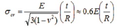
where E is the Young's modulus, n - the Poisson ration of the isotropic material, t - the thickness and R - the radius of the shell. Due to the importance of the current topic and wide variety of applications in the engineering industry there are a number of investigations that are published in the literature every year.
The following are some important general observations from the open literature available in research journals, conference proceedings and technical bulletins published by industries (Von Karman et al., 1940).
The above observations indicate that the classical theory of buckling will not fully take into account certain factors that will influence the buckling phenomenon leading to the large difference between the theory and experiments. This stimulated intensive research into the phenomena of buckling in thin-shell structures. As a result, analysis of buckling in thin cylindrical shell structures remains an active research area even today contributing to a number of research papers in archival journals. This section presents an over view of pertinent literature contributed by other researchers in the area of buckling of thin cylindrical shells subjected to different geometric parameters and loading conditions. This overview also includes numerical simulations and experimental studies.
Von Karman et al. (1940) investigated the influence of curvature on the buckling characteristics of structures. They had an early breakthrough in understanding the features of shell buckling. They pointed out that the behavior of a cylindrical shell under axial compression involves strong non-linear features, and this leads to a sharp decrease in load-carrying capacity after the peak value of load has been reached. Von Karman and his colleagues successfully simulated some of the main features of shell buckling with some simple experiments on a model column that was physically restrained by a slightly nonlinear spring which represented the “stretching” behavior of the shell.
Koiter (1945) developed and presented, in his doctoral thesis, the general theory of elastic stability taking non linearity into account, which is capable of determining the stability of equilibrium of a structure at or near the bifurcation buckling point. His scheme involves unstable equilibrium paths emerging from a bifurcation point for the initially perfect cylindrical shell and the presence of small geometrical imperfections having a disproportionately large effect in reducing the maximum load. His work became a conventional practice for engineers at that point of time. This scheme connects analytically.
Arbocz (1974) studied extensively the effect of initial imperfections on the shell stability with a view to predict buckling loads for cylindrical shells on the basis of precisely measured geometric imperfections. However, these studies had a very limited success.
Abramovich et al. (1991), also attempted to investigate the influence of initial imperfections on the buckling of stiffened cylindrical shells under combined loading again with little success. The concepts of “non-linearity” and “imperfection sensitivity” are now being widely accepted for providing an explanation for the buckling performance of thin-shell structures. “Imperfection-sensitivity” does not adequately provide a satisfactory explanation of the observed buckling loads in relation to geometric parameters like radius and thickness. Therefore the design engineers need a tool to quickly proceed with the design process.
Yamaki (1984), conducted a numerical study on the buckling of circular cylindrical shells subjected to external pressures. His results have shown that in the case of 2 relatively long shells with a parameter 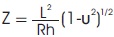 larger than 100, the critical load parameter pRL2 / πD and the corresponding circumferential wave number nπL/R are almost proportional to Z1/2 and Z1/4 respectively L, R, h, υ and D are the length, the radius, the thickness, and poissons ratio and bending stiffness of the shell; p is the external pressure. Besides, as Z increases, the critical values tends to limit which depend solely on the axial edge constraints. In addition, studies involving experiments, theoretical calculations and numerical simulations have shown that the buckle shape of the circular cylindrical shells under pressure involves variations, which are much faster, in the circumferential direction than in axial one if L/R is not too large.
Heyman (1977) documented the work on equilibrium of shell structures. It is envisaged that the kind of stress-free, geometric imperfections considered in the conventional theory proposed by Koiter and Arbocz are by no means the only kind of practical imperfections that may arise in the actual construction of shells. Then an alternative candidate for significant imperfection while the shell is under construction is the initial stress. In principle, this initial stress, may cause a shell to buckle under a very small applied load or even without application of any load.
Lancaster et al. (1998) tried to resolve the paradoxical buckling behavior of a thin cylindrical shell under axial compression with an aim to investigate the effect on the buckling load of imperfections in the form of local initial stress. They considered local initial stresses are probably more typical of practice than purely geometric ones. They conducted experiments on a vertical “Melinex” cylinder of diameter 0.9 m and height 0.9 m with r/t ratio approximately equal to 1800. The boundary conditions considered in their experiment are that the upper and lower edges of the cylinder were clamped to the end disks by means of circumferential belts. Their results showed that the buckling load is not sensitive to imperfections. The test results with or without deliberate imperfections showed very little scatter. Even gross imperfections in the form of large stable dimples at zero load reduce the peak load on an average by only about 12%.
Park and Kyriakides (1996), in their study “On the collapse of dented cylinders under external pressure” attempted to identify the major factors that affected the collapse pressure of pipes that are diameter-to-thickness ratio D/t, the Young's modulus and yield stress of the material in the circumferential directions and initial imperfections in the form of ovality and thickness variations in the wall.
Bai et al. (1997) in their study on Finite element analyses of the collapse behaviour for long, relatively thick-walled metal tubes are presented under combined external pressure, tension and bending loads. The effects of initial ovality, residual stress, strain-hardening, yield anisotropy and load paths have been accounted for in the analyses.
Collapse envelopes for thick tubes under combined external pressure, tension and bending loads are presented in the form of pressure-moment-tension interaction, pressure-tension-curvature interaction and pressure-axial strain-curvature interaction. Factors affecting collapse envelopes are identified by means of parametric studies. The analysis procedure has been validated using experimental results.
The aim of this project is to estimate the buckling loads and buckling stresses of thin cylinder shells in two different cases, one is subjected to both axial and lateral pressure, and in another case it is subjected to only lateral pressure. The General procedure is pre-processing, simulation and postprocessing and is explained in Figure 2.
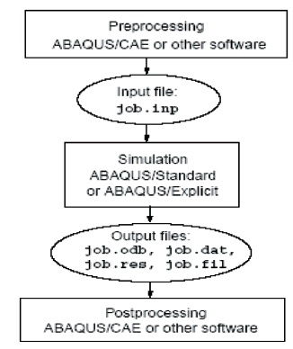
Figure 2. Flow Chart in Abaqus
The dimensions of the cylindrical shell used were of radius of 0.05 m, length of 0.5 m and thickness of 0.001 m Figure 3 shows the model of cylindrical shell with Solid Works.
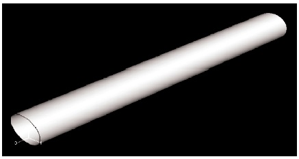
Figure 3. Modelling the Cylinder Shell with Solid Works
These parameters were varied for different cases when subjected to axial and transverse or lateral pressure conditions. The analysis had been done for three different material models, those are mild steel, titanium alloy, aluminium alloy. The lateral pressure applied is 100 Pa where as axial load is 10 kPa. The boundary conditions were fixed at both ends for cylinder subjected to transverse pressure only and pinned when it is subjected to both axial, transverse pressure. Figure 4 & 5 shows the pre-processing stage where meshing and boundary conditions are applied.
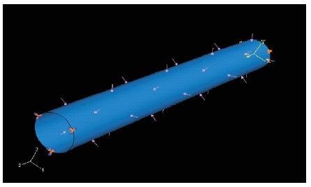
Figure 4. Boundary Condition & Loads of the Cylindrical Shell
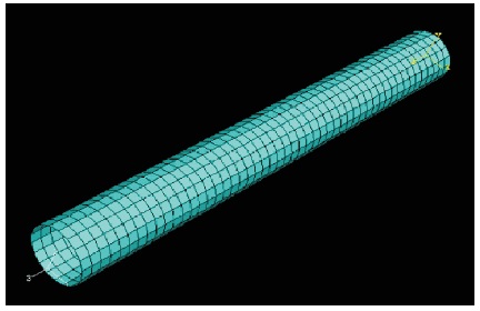
Figure 5. Meshing of the Model Cylinderical Shell
Mild steel : E=200 GPa, n=0.3
Titanium alloy (6A14V) : E=100 GPa, n=0.36
Aluminium alloy (7075-T6) : E=70 GPa, n=0.34
The simulation run as a background process in which it solves the numerical problem defined in the model. The output files from a stress analysis problem include displacements and stresses that are stored in binary files ready for post processing. Depending on the complexity of the problem being analyzed and the power of the computer being used, it may take anywhere from seconds to days to complete an analysis run. (Abramovich et al., 1991).
Cylinder of mild steel is subjected to axial compression and lateral pressure for various radius under pinned condition (Bai et al., 1997). Buckling analysis of Mild steel results are shown in Figure 6 to Figure 21. Mild steel is subjected to lateral pressure for various radius under fixed condition. Case cylinder of mild steel is subjected to lateral pressure for various lengths under fixed condition.
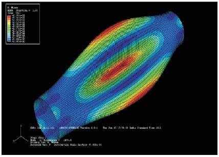
Figure 6. Deformed Shape when L=0.5 m, with Buckling Stress 34.7 GPa, Mode 1
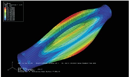
Figure 7. Deformed Shape when L=0.7 m, with Buckling Stress 24.5 G Pa, Mode 1
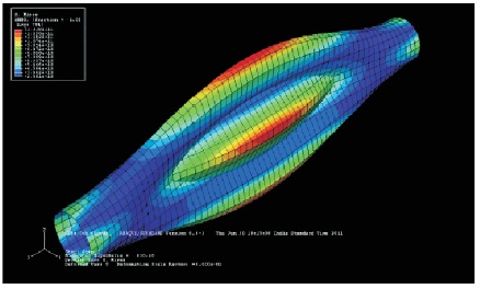
Figure 8. Deformed Shape when L=0.9 m, with Buckling Stress 28.7 G Pa, Mode 1
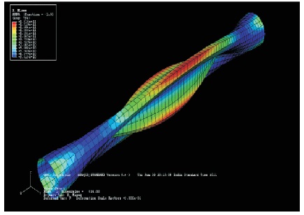
Figure 9. Deformed Shape when L=0.9 m, Mode 2
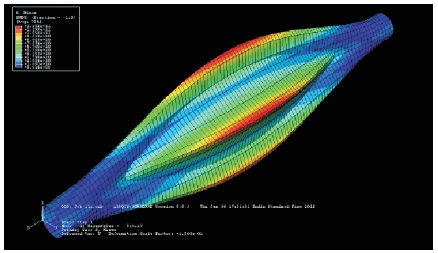
Figure 10. Deformed Shape when L=1.5 m with Buckling Stress 8.9 G Pa, Mode 1
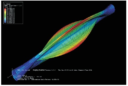
Figure 11. Deformed Shape when L=1.5 m, Mode 2 Deformed Shapes for Various Thickness
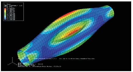
Figure 12. Deformed Shape when t=00.1 m, with Buckling Stress 18.96 G Pa, Mode 1
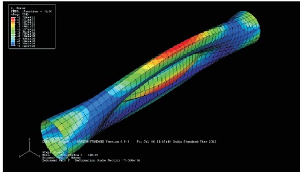
Figure 13. Deformed Shape when t=0.001 m, Mode 2

Figure 14. Deformed Shape when t=0.015 m, with Buckling Stress 157.6 GPa, Mode 1
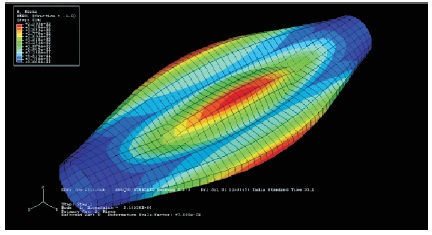
Figure 15. Deformed Shape when t=0.020 m, with Buckling Stress 203.1 Gpa
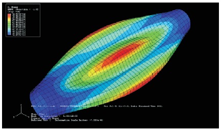
Figure 16. Deformed Shape when t=0.025 m, with Buckling Stress 214.2 G Pa
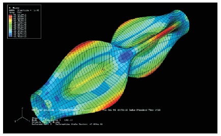
Figure 17. Deformed Shape when r=0.05 m, with Buckling Stress 25.4 G Pa
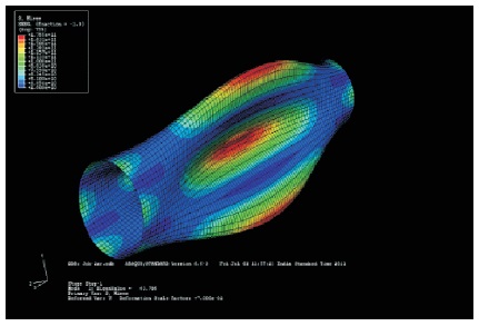
Figure 18. Deformed Shape when r=0.07 m, with Buckling Stress 25.9 G Pa
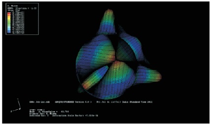
Figure 19. Deformed Shape when r=0.07 m, with Buckling Stress 57.72 G Pa, Mode 2
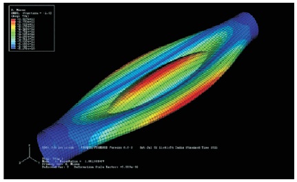
Figure 20. Deformed Shape when r =0.2 m, with Buckling Stress 21.5 G Pa
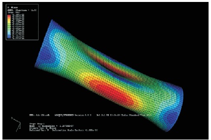
Figure 21. Deformed Shape when L =0.2 m, with Buckling Stress 196.8 G Pa, mode 1
Titanium alloy is subjected to lateral pressure for various radius under fixed condition. Cylinder of titanium alloy is subjected to lateral pressure for various thicknesses under fixed condition. Cylinder of titanium alloy is subjected to lateral pressure for various lengths under fixed condition. Buckling analysis of titanium alloy is shown in Figure 22 to Figure 27.
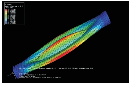
Figure 22. Deformed Shape when r=0.03 m, with Buckling Stress 29.12 G Pa, Mode 1
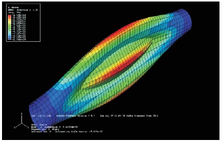
Figure 23. Deformed Shape when t=0.008 m, with Buckling Stress 15.91 G Pa, Mode 1
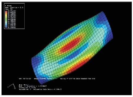
Figure 24. Deformed Shape when L=0.2 m, with Buckling Stress150.8 G Pa, Mode 1
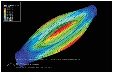
Figure 25. Deformed Shape when r=0.03 m, with Buckling Stress 29.06 G Pa, mode 1
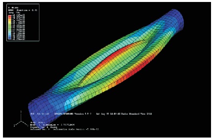
Figure 26. Deformed Shape when t=0.008 m, with Buckling Stress 11.6 G Pa, Mode 1
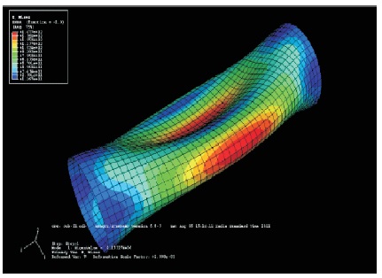
Figure 27. Deformed Shape when L=0.2 m, with Buckling Stress 167 G Pa, Mode 1
In a similar way all the conditions are applied for the materials and simulation is done and the obtained values are tabulated in the results in Table 1 to 12.
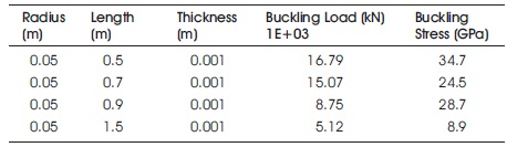
Table 1. Cylinder Subjected to Axial & Lateral Pressure by Varying Length
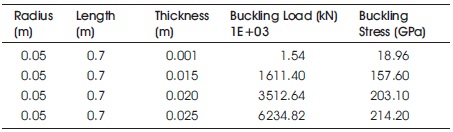
Table 2. Cylinder Subjected to Axial & Lateral Pressure by Varying Thickness
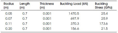
Table 3. Cylinder Subjected to Axial & Lateral Pressure by Varying Radius
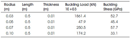
Table 4. Cylinder Subjected to Lateral Pressure by Varying Radius
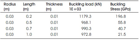
Table 5. Cylinder Subjected to Lateral Pressure by Varying Length
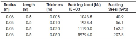
Table 6. Cylinder Subjected to Lateral Pressure by Varying Thickness
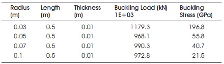
Table 7. Cylinder Subjected to Lateral Pressure by Varying Radius
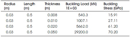
Table 8. Cylinder Subjected to Lateral Pressure by Varying Thickness
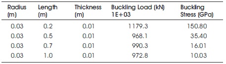
Table 9. Cylinder Subjected to Transverse Pressure by Varying Length
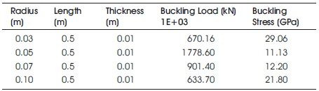
Table 10. Cylinder Subjected to Lateral Pressure by Varying Radius
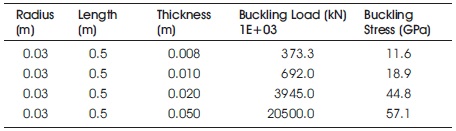
Table 11. Cylinder Subjected to Lateral Pressure by Varying Thickness
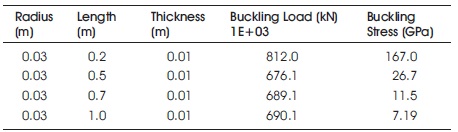
Table 12. Cylinder Subjected to Lateral Pressure by Varying Length
The deformation shapes shown in Figures 6 to 11 is in the form of sine wave pattern. This pattern remains unchanged for larger lengths. So it is identified that the length has effect on the buckling stress. It is also verified from the buckling equation where there is no length parameter. This is shown in Table 1.
The deformations of Figures 12 to 16 are also in the sine wave pattern. The deformation area has been increased when there is increase in the thickness. The buckling stress increased from 18.96 to 214.2 Gpa. So it is identified that as the thickness is increasing the buckling stress is also increasing. This is also verified from the buckling equation.
The deformations of Figures 17 to 19 are also in the sine wave pattern. The number of half waves has been increased along the circumferential direction when there is increase in radius. The buckling load decreased from 1470 to 156.6 kN when radius is increased from 0.05 to 0.2 m.
The deformations of Figures 20 to 22 are in the sine wave pattern. The number of half waves has been increased along the circumferential direction when there is increase in radius. The buckling loads are decreased from 1861.4E+3 to 174.2E+3 kN, when there is increase in the radius from 0.03 to 0.1 m.
From Table 5, we can see that the deformations are in the sine wave pattern. This pattern remained unchanged for larger lengths as seen in Table 5. The buckling load is decreased to 1179.3E+3 to 972.8E+3 kN.
The deformation has been increased when there is increase in thickness. The buckling load increased from 1043.5E+3 to 59794E+3 kN, when there is increase in thickness from 0.008 to 0.05 m as seen in Table 6.
The number of half waves has been increased along the circumferential direction when there is increase in radius.
This is depicted from Table 7. The buckling load is decreased from 1005E+03 to 90.9e+3 kN when there is increase in the radius from 0.03 to 0.1 m.
The deformation has been increased when there is increase in thickness. The buckling load is increased from 540E+03 to 29200E+03 kN when there is increase in thickness from 0.008 to 0.05 m as in Table 8.
The deformation remained unchanged for larger lengths as shown in Table 9. The buckling load is decreased from 1179.3E+3 to 972.8E+3 kN when there was increase in length from 0.2 to 1.0 m.
From Table 10 we can depict that the number of half waves has been increased along the circumferential direction when there is increase in radius. The buckling load is decreased from 670.1E+3 to 633.7E+3 kN when there is increase in radius from 0.03 to 0.1 m.
The deformation has been increased when there is increase in thickness as shown in Table 11. The buckling load 20500E+3 kN is maximum at thickness 0.05 m. The deformation remained unchanged for larger lengths as seen in Table 12. The buckling load decreased from 812E+03 to 690E+3 kN when there is increase in length from 0.2 to 1.0 m.
The results obtained from the simulation are compared with the existing steel material and the best suitable material is selected from the simulation results. Only analysis based results are discussed and the theoretical results may not give the appropriate values. Though we can compare and note an error of 4% to 5% result variation when compared with the analytical results when the analysis is done by considering the perfect loading conditions.
Similarly the graphs for all other materials can be drawn by taking the different parameters. Figure 28, 29 & 30 shows the buckling stress variation with change in length, thickness and radius respectively.
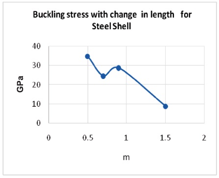
Figure 28. The Buckling Stress Variation with the Change in Length
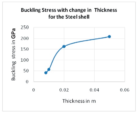
Figure 29. The Buckling Stress Variation with the Change in Thickness
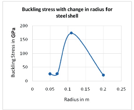
Figure 30. The Buckling StressVariation with the Change in Radius
The buckling stress from the Simulation results shows that the buckling stress has been decreased from 34.7 to 8.9 GPa when there is a increase in the length from 0.5 to1.5 m during the combined loading conditions. The buckling stress has been increased from 18.9 to 214.1GPa when there is a increase in the thickness from 0.001 to 0.025 m during the combined loading conditions. The buckling stress has been decreased from 25.5 to 21.5 GPa when there is a increase in the radius from 0.05 to 0.2 m during the combined loading conditions. From all the cases mild steel cylinder shell is found to have maximum buckling stress 207.8 GPa compared to titanium alloy of 70.2 GPa and aluminum alloy of 57.1 GPa at the thickness of 0.05 m. The stress decreases when there is a increase in the length during the combined loading conditions. The buckling stress has been increased with the increase in the thickness values during the combined loading conditions and the buckling stress was decreased when the radius values increases. From the entire analysis it is shown that mild steel cylinder shell is found to have maximum buckling stress compared to titanium alloy and aluminium alloy. The same analysis with Experimentation can be performed by considering composite materials as they are high strength compared to the existing materials. It is then compared with mathematical equations and can be evaluated.