


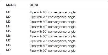
Table 1. Description for the Various Models Considered
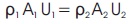
4.1.2 Momentum and Bernoulli's equation
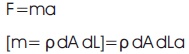
The momentum equation is also called as equation of motion as it is related to Newton's 2nd equation of motion i.e. the levy of change of momentum of the fluid particles must be same as the forces acting along the stream.
F = mass × acceleration
Now,
Consider a small element of the fluid from the entire flow.
Let,
dA = cross sectional area of the considered fluid element.
dL = length of the fluid element.
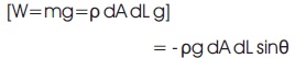
dW = weight of the fluid element.
u = velocity of the fluid element.
p = pressure of the fluid element.
Assume that the fluid is steady, non-viscous, incompressible, so that the frictional losses are zero and the density of the fluid is constant.
The different forces acting on the fluid are,
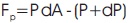
- Pressure force acting in the direction of the flow (PdA).
- Pressure force acting in the opposite direction of the flow [(P+dP)dA].
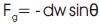
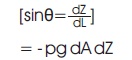
- gravity force acting in the opposite direction of the force (dWsin θ).
Therefore,
Total force = gravity force + pressure force
The pressure force in the direction of flow,
The gravity force in the direction of flow,
The net force in the direction of flow,
We have,
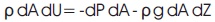
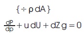
(Euler's equation of motion).
By integrating the Euler's equation, we get the Bernoulli's equation,
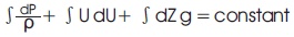
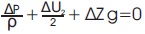
(Bernoulli's equation)
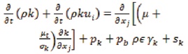
4.1.3 Kappa – Epsilon Model
The kappa – epsilon energy equation is used for the analysis of the turbulent flow. Kolmogrov has first introduced it in the year 1942. Harlow and Nakayama redefined and developed a new set of forced flow equations for the kappa – epsilon energy equations,
5. Regression Analysis
In the present work, the software simulated data has been compared with the regression data. Regression generally describes the relation in between an independent variable and a dependent variable. This simulated data has been referred to generate an equation which can be used to find the maximum outlet velocities of the considered models. After substituting the values from the simulated data in the proposed final equation, an error can be identified if any (Eiamsa-ard & Promvonge, 2008; Fluent, 2005; Kim & Lee, 2007; Launder & Spalding, 1972; Luo et al., 2005; Promvonge, 2008).
velocity=1.544+0.03921 (degree)-0.000251 (degree2)
6. Results and Discussions
The amount of heat transfers from a pipe geometry to the surrounding environment or any other medium can be intensified by placing the intruders or the successive promoters along the internal surface of the considered geometry (Ramadhan et al., 2013). The desired grooved geometries are provided with the nozzle so as to increase the heat swapping in further cases. These nozzle arrangement is attached for the triangular grooved geometry since they are found to be the best in terms of heat transfer as they have a lower groove depth ratio (Ramadhan et al., 2013; San & Huang, 2006). These modified geometries are analyzed using the ANSYS – FLUENT software. The geometries are applied with solving equations such as the energy equation, Bernoulli's equation and k – epsilon equation. The inlet velocity has been taken as constant i.e. 0.5 m/s for all the considered geometries (Ceylan & Kelbaliyev, 2003; Dalle Donne & Meyer, 1977; Jaurker et al., 2006; Kelbaliyev, 2003; Lorenz et al., 1995). The Figures of the results depicted that the heat swapping contours along with the velocity and o pressure contours are best for the cases in between the 40 & 50o angles of convergence of nozzle. Due to the nozzle arrangement at the extremity of the pipe geometry ultimately leads to a appreciable amount of increase in regards to the heat swapping contours along the direction of the flow.
The generated results depict that the maximum variations can be observed in between the models M4 & M5 i.e., between the 40o and 50o angle of convergence. The triangular grooves along the internal surface of the pipe contribute to an surge in the temperature contours. In addition to the triangular grooves, the nozzle arrangement at the extremity of the pipe also contribute to an higher amount of increase in the temperature contours thereby maximum of heat is transferred in between the geometry and the environment or the geometry and the working medium (Bilen et al., 2009; Chaube et al., 2006; Kiml et al., 2004; Sparrow et al., 1980; Webb et al., 1971). These modified geometries can be applicable in the industries for larger intends.
From Figure 1, we can observe the increase in the velocity at the central portion of the geometry and contribution to the heat transfer along the surface from the Figure 3. Since the pressure and velocity are inversely proportional to each other, we can observe the pressure drop from the Figure 2 and Figure 6. Figure 4 & 5 shows the temperature and velocity contours of M5.
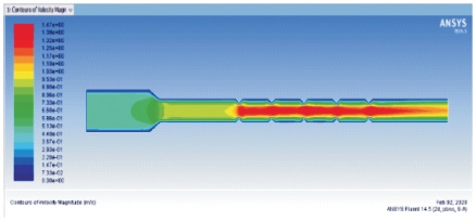
Figure 1. Velocity Contours of Model M4
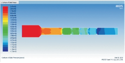
Figure 2. Pressure Contours of Model M4
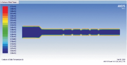
Figure 3. Temperature Contours of Model M4
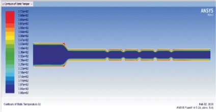
Figure 4. Temperature Contours of Model M5
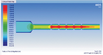
Figure 5. Velocity Contours of Model M5
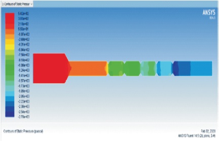
Figure 6. Pressure Contours of Model M5
The Table 2 displays the temperature contours for the models considered with different angles of convergence for the nozzle. Similarly the Table 3 & Table 4 displays the velocity and pressure contours respectively. We can observe the increase in the heat swapping contours of models M4 and M5. The simulated data has been compared with the regression data generated using the final derived equation. The comparison can be observed in Table 5. The comparison has found out to be accurate enough with 98.8% accuracy (Chaube et al., 2006; SundÉn, 2000; Tatsumi et al., 2003; Yang & Hwang, 2004). The R-Sq details are tabulated in Table 6.
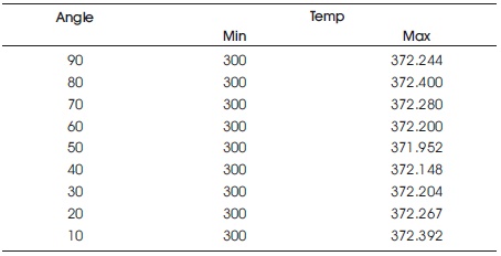
Table 2. Temperature Contours of the Considered Models
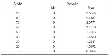
Table 3. Velocity Contours of the Considered Models
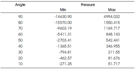
Table 4. Pressure Contours of the Considered Models
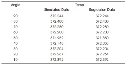
Table 5. Comparison between the Simulated and Regression Data
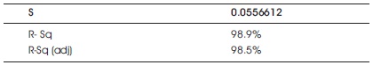
Table 6. R – Sq Details
Conclusion
The pipe geometries with the triangular grooves has been attached with a nozzle at the end of the pipe. The analysis has been carried out in the ANSYS – FLUENT software for the comparison of velocity, pressure and temperature contours. It can be declared that the nozzle arrangement along with the triangular grooves with the internal surface the pipe geometry can lead to a considerable amount of increase in terms of all the contours. The heat swapping contours displayed an increase of 10.91% and velocity contours displayed an increase of 6.15%. The software simulated data when compared to the regression data, depicts the accuracy and the applicability of the present work. The experimental data can be referred for the applications in larger intends.