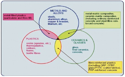
Figure 1. Evolution of Composites (Harris, 1999).
A wheel rim is one of the most important parts of a vehicle. Invention of the wheel was amongst a major breakthrough in early days. A wheel rim, along with chassis or the frame of the vehicle holds the load of the automobile and its passengers providing cushioning effect. In this paper performance of different materials used in making wheel rim are checked through CAE software. Different alloys and materials are tested which can be used for the alloys of vehicles in the future. Alloy wheels differ from steel wheels because of their lighter weight, which improves the driving and handling of the vehicle. The material chosen for making wheel spokes needs to have certain qualities as to be suitable for the use. The properties are thermal conductivity, machine processing, corrosion resistance, characteristics of casting, low temperature, high damping property, excellent lightness, and recycling, etc. A wheel rim is subjected to many loads which causes damage to the rim. Increasing the performance of rim can increase the overall performance of the vehicle. With new researches, materials have evolved. The evolvement of the material has led to the invention of composite material. A composite material has better properties as compared to alloys and other materials. Composite material has better strength, low weight and other mechanical and chemical properties. Superiority of composite materials is proved by the results in this manuscript. By using composite material the properties gets improved as a result of which overall vehicle performance is improved.
The invention of the wheel falls into the late Neolithic, and may be seen in conjunction with other technological advances that gave rise to the early Bronze Age. Note that this implies the passage of several wheels-less millennia even after the invention of agriculture and pottery.
The very first evidence of wheel is found in half of 4 century BCE (Wheel, n.d.). The earliest well dated depiction of a wheeled vehicle was in 3500-3350 BCE clay pot excavated (Anthony, 2007). Wheel in times of early evolution of men had been an important discovery. Wheel alone was not only used for vehicles, but also for pottery, spinning, weaving. Later on, wheel evolved to be assembled in carts and wagons and further to be fitted in vehicles which were pulled by animals.
The invention of the wheel proved to be one of the most important inventions of all times. Historians of today see the introduction of the wheel as the real genesis of any old civilization. Wheels were discovered in primitive times by ape mans. It helped men for ages and ages for transportation and other daily uses. With time wheel developed further and further. From hand pulling carts to animals attached cart wheel rim, it became a very important component for primitive men.
The choice of material has always been an important factor for the design of wheel rim. Wheel has evolved from wood to steel and now to alloys of magnesium and aluminium. A lot of variety has been seen over a decade for manufacturing wheel as stone, wood to metals like steel to non ferrous materials like Al alloy and mg alloy. Apart from the material, design of wheel rim also gone under various design modification. It was know from historians that the design of the wheel in medieval period was of a disc which later on took shape of a spokes wheel, made of wheel usually used in horse pulled wagons.
As with the development, the thin wheel rim was made with steel, to flat steel discs and finally to the stamped metal configurations. Modern cast and forged aluminium alloys rims of today's modern vehicles are historically successful designs arrived after years of experience and extensive field testing.
With development of ages, wheel took on many forms but staying in its shape. Wheel served many purpose over years. But today in modern world it is definitely the component of progress. Vehicles being very important and so are the wheel. A vehicle can moved without engine, can run on different fuels be it gasoline, diesel or electricity. But no alternate has been found for the wheel of vehicle instead wheel has evolved with its usage on basis of design and material.
The study which is being carried out is for further development of wheel rim on material basis. Previously, material used for wheel rim was steel which certainly had some drawbacks. Steel has been taken over by alloys of aluminium and magnesium for over two decades. The need of alloy wheel came with usage of vehicle on multi terrain. Alloys have properties of good machining so they can be manufactured in various designs as they are in demand from the end users. NADCA (North American Die Casting Association, 2009) clearly explains about Aluminium, (Al) die casting alloys have a specific gravity of approximately 2.7 g/cc, placing them among the lightweight structural metals. The majority of die castings produced worldwide are made from aluminium alloys. Six major elements constitute the die cast aluminium alloy system i.e., silicon, copper, magnesium, iron, manganese, and zinc. Each element affects the alloy both independently and interactively.
To increase the performance of the wheel rim, the rim should be made of lighter material which at the same time should have more strength, durability and endurance. These properties cannot be achieved with a single alloy. By mixing two or more alloys these properties can be attained. The material so formed is called composite material.
The concept for a light weight wheel arose in the mind of Ressa (2013) for weight reduction in a formula SAE competition vehicle. The vehicle was a part of a collegiate race series run by the society of automotive engineers where students design, build, and race a scaled formula style open wheel race car. The wheel was selected for a weight reduction out of the many other components because in addition to a weight reduction, a redesigned wheel rim offers performance benefits as well.
Composite materials are not available in nature. Composite materials is an invention not discovery. It is made by infusing two or more alloys together. Composite material is used in form of ply and the use of composites in manufacturing could be briefly understood by the study of Ressa (2013). The evolution of composite material could be briefly understood in Figure 1 as illustrated by Harris (1999). The evolution of composite materials started from the basic materials to plastics and ceramics.
Figure 1. Evolution of Composites (Harris, 1999).
Wheel rim alone is not sufficient to move the vehicle. It is the wheel with tyre that bears the load and moves the vehicle. A complete wheel assembly has a wheel rim with spokes and rubber inflated tyre (tyre tube also included in case if the tyre is not tubeless). This complete arrangement is then fixed to axle hub which is the driving portion. Wheel rim is basically a cylindrical portion in the centre of the wheel which gets connected to axle hub to bear load and make the tyre move. A lot of consideration is made in manufacturing of the wheel rim from design to material to regulations and specifications.
Spoke wheels: In wire spoke wheels, the end of the spokes are connected to hub of the wheel and other end is connected to wheel rim or the rim circumference. The spokes are stiffer than a typical wire rope, and they function mechanically the same as tensioned flexible wire. The spokes keep the rim true while supporting applied load. Wire spoke wheel rims are also called Wire wheels, wirespoked wheels, tension spoked wheels, or suspension wheels. (Brown, 1997; Forester, 1980; Walker, 1920).
Steel Disc Wheels: This type of wheel rim is still in practice. Many of the four wheeler vehicles uses steel disc wheel. The reason for using steel disc rim is because of the low cost of rim. Many new vehicles come with steel disc. The steel disc is joined with the rim by welding process. The disc becomes a member to be fixed on hub and also a load carrying member.
Alloy Rim Wheels: Alloy wheels are one of the most commercially used wheels these days. The most common material used in category of lighter alloys is magnesium and aluminium. Alloy wheels are lighter in weight and are also used for cosmetic purpose as they are available in many designs and are very much appealing in look. Alloy wheels come in the category of non ferrous material. Al and Mg alloy are lighter, soft and more ductile than steel. Steel is also an alloy of carbon and iron but for wheels the term is what reversed and Al and Mg are kept in category of non ferrous alloys. Aluminium and magnesium would be discussed further in material classification.
Steel: Steel is an alloy of iron and carbon. Wheel rims are mostly made of forged steel. Steel was the only material for decades to be chosen as material for wheel rim because of its properties. The carbon content of steel is between 0.002% and 2.1% by weight for plain iron-carbon alloys. These values vary depending on alloying elements such as manganese, chromium, nickel, iron, tungsten, carbon and so on. Basically, steel is an iron-carbon alloy that does not undergo eutectic reaction. In contrast, cast iron does undergo eutectic reaction, suddenly solidifying into solid phases at exactly the same temperature. Too little carbon content leaves (pure) iron quite soft, ductile, and weak.
Magnesium Alloy: Magnesium alloy is about 30% lighter than aluminium and also admirable as for size stability and impact resistance. However its use is mainly restricted to racing, which needs the features of weightlessness and high strength. It is expensive when compared with aluminium (Chaitany & Murty, 2015). Mg alloys are well known for the following properties (Theja & Krishna, 2013).
Aluminium Alloy: Aluminium wheels have better performance than steel wheels. Aluminium is a metal with features of light weight, low heat conductivity, low corrosion, and low temperature. Aluminium can also be recycled making it environmental friendly. Aluminium’s light weight provides vehicles optimized performance in form of bettering steering control and low fuel consumption. It has been seen that, at the time of application of break a large amount of heat is dissipated and if the material is not a good conductor of heat then there are chances of brake failure. Aluminium being a good conductor of heat omits the risk of brake failure. Aluminium has good machinability which makes manufacturing of the wheel rim easy compared to steel. With a single piece of aluminium a wheel rim could be made out with proper machining. The forming procedure is billet, disk type forging, bore piercing, spinning and heat treatment and machining. (Kumar et al., 2014).
Aluminium alloy is a metal with features of excellent lightness, thermal conductivity, physical characteristics of casting, low heat, machine processing and reutilizing, etc. This metal’s main advantage is decreased weight, high precision and design choices of the wheel (Chaitanya & Murty, 2015).
Titanium Alloy: Titanium being in development stage has certain disadvantages as bad machining properties, costlier and not easily designable. Though, it is very admirable metal for corrosion as it is highly resistant and strength of titanium is about 2.5 times that of aluminium. Titanium alloy have high tensile strength and toughness. It is light in weight and can withstand extreme temperature. The reason which limits the use of titanium is its cost. Because of the cost of titanium its use has been limited to sectors like defense, medical, aircraft and space craft. The composition for most of the applications of titanium is 4% and 6% of vanadium and aluminium respectively. Titanium is strong and lighter at the same time. It is as strong as low carbon steel but 45% lighter at the very same time. Being of twice strength as of aluminium but only 60% heavier as compared to double weight.
Composite Material: As told by Harris (1999), ferrous and non ferrous metals with their advantages have some deficiencies. As if it's strong it is heavier and when it's light in weight its weak. Composite material is so combined in a way as to enable their virtues while minimizing to some extent their virtues. The optimization of composite material puts a designer to ease, as he is released from the burden to choose from the convectional materials. Many a times a designer wishes to have a material with a mixture of multiple properties and this case is not possible with convectional materials available. With the use of composite material, designer gets the power to combine material and get a material of required qualities. Those qualities could be strong and light weight. And because of the ease with which complex shapes can be manufactured, the complete rethinking of an established design in terms of composites can often lead to both cheaper and better solutions.
Harris (1999) explained the manufacturing process of composite metal matrix about the basic attributes of metals reinforced with hard ceramic particles or fibers are improved. Improved creep and fatigue resistance, strength and stiffness, wear and abrasion resistance, and increased hardness, combined with the possibility of higher operating temperatures than for the unreinforced metal.
Some of the techniques that have been described in detail are,
Drop Centre: The center section of the rim being lower than the two outer edges. This allows the bead of the tire to be pushed into the low area on one side while the other side is pulled over and off the flange.
Tire Bead Seat: Tire bead is the term for the edge of a tire that sits on the wheel. Wheels for automobiles, bicycles, etc. are made with a small slot or groove into which the tire bead sits. When the tire is properly inflated the air pressure within the tire keeps the bead in this groove. Bead seat approaches in contact with the bead face and it is a part of rim which holds the tire in a radial direction.
Fixed Flange: A flange is an external or internal ridge, or rim (lip), for strength, as the flange of an iron beam such as an Ibeam or a T-beam; or for attachment to another object, as the flange on the end of a pipe, steam cylinder, etc., or on the lens mount of a camera; or for a flange of a rail car or tram wheel.
Hump: The rim beading, in this case something like 'hump'. It was introduced with the conversion to tubeless tyres. It prevents the tire slipping off into the deep bed and the sudden loss of a lot of air i.e. during hard cornering.
Wheel Well: This is a part of rim with depth and width to facilitate tire mounting and removal from the rim. Figure 2 shows the nomenclature of wheel rim.
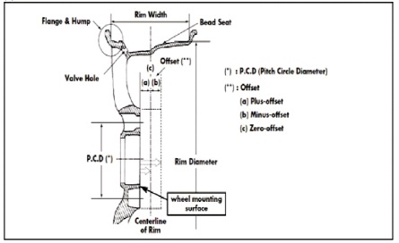
Figure 2. Nomenclature of Wheel Rim
Offset: The offset of a wheel is what locates the tire and wheel assembly in relation to the suspension. The distance between the centre line of rim and hub mounting surface is the called as offset of wheel rim. The three types of offsets are mentioned in Figure 3.
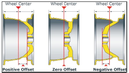
Figure 3. Showing Different Offsets in a Wheel Rim
Positive offset: Most of the rims manufactured have positive offset. A positive offset is one which has the hub mounting surface on the straight side or of the opposite side of the brake mounting.
Zero offset: When the hub mounting surface is centered with center line of the wheel rim, this type of offset is termed as zero offset.
Negative offset: If the hub mounting surface is on the brake side of the centre line of rim it is considered as negative offset deep dish. Wheel is said to have negative offset when the hub mounting is on the brake side of the centre line of rim. Negative offset is also called negative offset deep dish.
CAD model is designed using Siemens Uni Graphics NX 10.0. NX 10 is widely used these days in industries and academics. NX is a very powerful tool used for cad modelling. CAD/CADD is computer added designing or computer added designing and drafting. CAD is basically designing a 3D model on computer using relevant software. The model is further used for conducting analysis or for manufacturing. Previously, there were several drawbacks related to engineering drawing; by the use of software the drawbacks have been eliminated. By the use of CAD, user can see 3D model of the product or entity designed. Based on the paper titled Design and Analysis of Wheel Rim using CATIA & ANSYS dimensions have been taken for this paper (Meghashyam et al., 2013).
Specifications of Model Wheel Rim:
Tire diameter (approx.) = 560 mm
Wheel size = 14 inches
Length = 86 mm
Flange shape = J
Rim width = 5 inches
Wheel type = disc wheel
Flange height = 0.68 inches
Tire type = radial
Aspect ratio = 65
Offset = 80.54
Modelling has been keeping the wheel rim to strict adherence to the rules and regulations. Model has been designed keeping safety and all the factors in mind that needs to be considered while designing a wheel rim. Wheel stands true to the nearest possible dimensions of a wheel rim used in any of the vehicles running on land today.
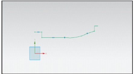
Figure 4. Sketch of Outer Periphery of Wheel

Figure 5. Outer Drum of Wheel Rim
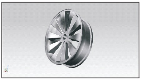
Figure 6. Completed Wheel Rim Design
Analysis is performed on Ansys 14.5 and done on structural basis. The file is imported in Ansys in parasolid format or IGES format. If the model needs any clean up, it is done in geometric modelling, then the model is moved to meshing. Topology optimization of the CAD model could also be done for the removal of extra material. But, the CAD model of the Rim is based on standard dimensions so the model does not need topology optimization. The model is then meshed using defined methods (NADCA, 2015).
To perform analysis on the model certain boundary conditions are required. The conditions required for this study are the load considerations. Wheel rim is subjected to load which is a combination of dead weight of the vehicle along with weight of the passengers.
The average weight of the sedan= 1225.153 kg
This is the dead weight of the vehicle.
Capacity of a sedan 4 person (1 additional Person could also accompany)
Average weight of person=60 kg
Total weight of passengers=60*5
be total weight of passengers=300 kg
Total weight on wheel rims=1225.123+300
Total weight on wheel rims=1525.123 kg
Total gross weight=1525.123*9.81
Total gross weight=1461.5 N
Tire and suspension system reduces weight by 30%
So, the net weight would be
1461.5*0.7=10473 N
But, this load is divided on four wheels.
Reaction force on each wheel rim
10473/4=2618.25 N
Load subjected on each rim = 2618.25 N
Analysis was carried on Ansys for each material on basis of Von Misses (Equivalent Stress) and total deformation for the load condition is stated. Figure 7, 8, 9, 10, 11, 12, and 13 shows stress produced in tested materials. Whereas Figure 14, 15, 16, 17, 18, 19, and 20 shows the deformation during test in various tested materials. Figure 21 shows the maximum stress at hub ends Table 1 shows comparison of stress produced in various materials. Table 2 and Table 3 provide comparison of weight and deformation in the tested materials respectively. Epoxy and Kevlar can be used in the future replacing presently used steel because of their light weight and average deformation. Presently these materials are expensive but in the future they can be widely used for manufacturing of the rims. Steel showed minimum deformation but steel is bulky and it is difficult to be machined. Therefore alloys can be used in wheel rims by increasing their thickness to reduce their deformation. Based on the results it can be concluded that alloys are the best alternative for steel.
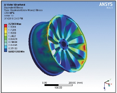
Figure 7. Von Misses for Steel
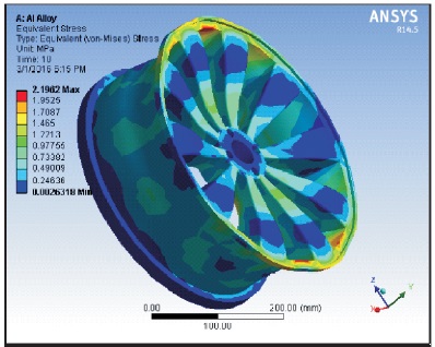
Figure 8. Von Misses for Al Alloy
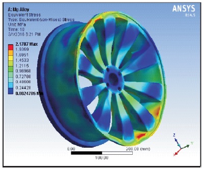
Figure 9. Von Misses for Mg Alloy
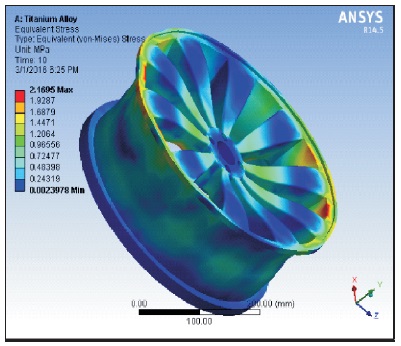
Figure 10. Von Misses for Ti Alloy
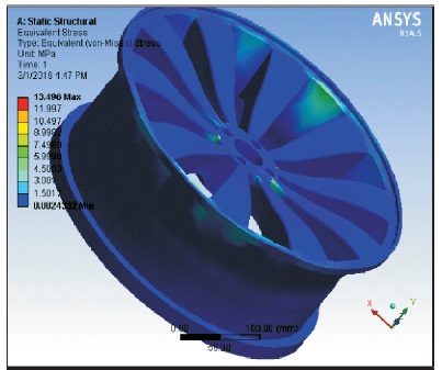
Figure 11. Von Misses for Carbon/Epoxy
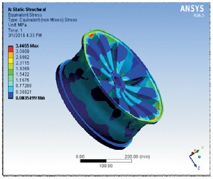
Figure 12. Von Misses for E-Glass
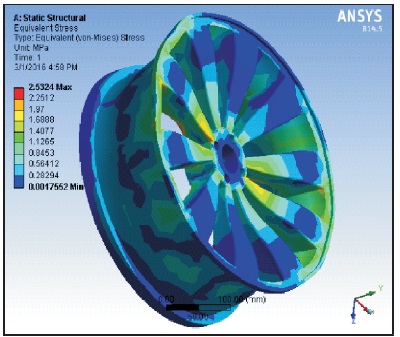
Figure 13. Von Misses for Kevlar
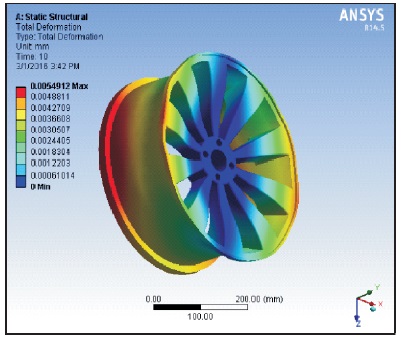
Figure 14. Deformation for Steel
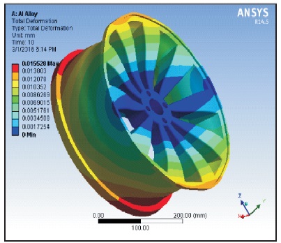
Figure 15. Deformation for Aluminium

Figure 16. Deformation for Magnesium
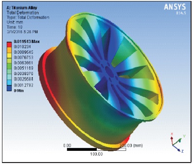
Figure 17. Deformation for Titanium
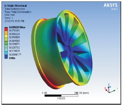
Figure 18. Deformation for Epoxy/Carbon
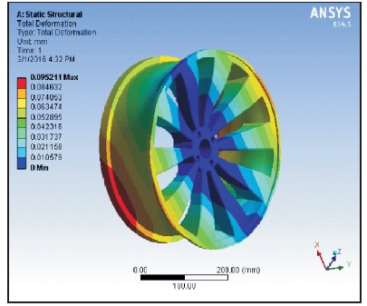
Figure 19. Deformation for E-Glass
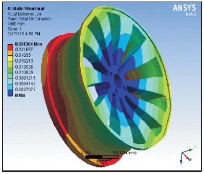
Figure 20. Deformation for Kevlar
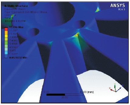
Figure 21. Maximum Stresses at Hubs End
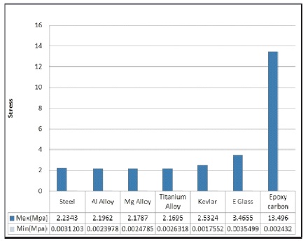
Table 1. Graph Showing Stress in Tested Materials
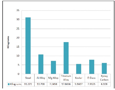
Table 2. Graph Showing Weight in Tested Materials
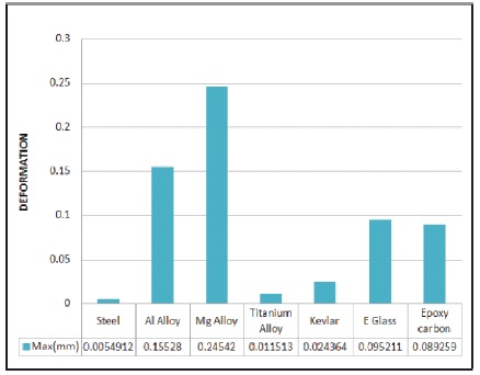
Table 3. Graph Showing Deformation of Tested Materials
The mathematical equation used for calculating the force is as follows.
The tractive force between a car wheel and the surface can be expressed as,

where,
F = traction effort or force acting on the wheel from the surface (N, lbf )
μt = traction - or friction - coefficient between the wheel t and the surface
W = weight or vertical force between wheel and surface (N, lb))
m = mass on the wheel (kg, slugs)
ag = acceleration of gravity (9.81 m/s2 , 32.17405 ft/s2)
The wheels are calculated in an static situation, therefore the effect of braking and bumping has been neglected.
The strength and resistance for deformation of steel is seen to be very good. But, there are certain problems related to steel. As wheel rim made of steel is very heavy as compared to other materials. Steel also have machining problems, while alloys are easily drawn into required shapes. There is not much difference seen in maximum and minimum stress developed in materials. Only Epoxy/ carbon has very high maximum stress but that also limited to very small portion or else Epoxy/carbon also have minimum stress, very close to all materials. Talking about deformation, steel has the least deformation followed by titanium alloy and Kevlar. The point to be noted is that the thickness of wheel rim has been constant throughout the test analysis. The Composite materials used have very light weight as compared to steel and alloys. The conclusion drawn is that the stress and deformation of composite materials are very close to steel and alloys with very low weight. If the thickness of composite materials could be increased, that would decreases stress and would increase resistance to deformation even at very high loads. Conclusion is based on the results from the test. Out of all the materials tested Kevlar and Epoxy carbon shows promise as the future material which can be used in automobiles. Composite materials being very light in weight shows sustainable results. Therefore, for future purpose composite with greater thickness could be used keeping weight as low as possible.