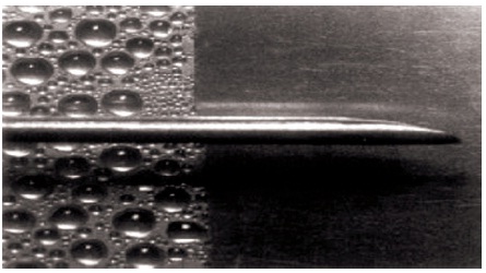
Figure 1. Dropwise and Filmwise Condensation
Dropwise condensation and filmwise condensation are experimentally investigated with the help of an experimental setup, by varying the mass flow rate of the cooling water. Dropwise condensation is achieved in a nickel-chromium coated copper tube, whereas filmwise condensation is seen in non-coated plain copper tube. The heat transfer coefficient for both the cases are calculated experimentally and theoretically by using the Nusselt's formula of condensation. From the evidence, the most effective method of condensation by varying the mass flow rate can be found. This is necessary to understand the theory of dropwise and filmwise condensation. The paper contains the experimental steps involved in performing the experiment, precautions, and final result of the experiment. An error analysis is to be made to check the accuracy of experimental and theoretical results.
Heat transfer plays a key role in wide range of industrial applications, such as power generation, thermal management, water harvesting, and desalination, where vapour condensation is a major issue to be taken into account. Fast droplet nucleation (Rose et al., 1999), efficient droplet departure from the surface and thermal resistance from the wall are some of the important factors to be considered in order to achieve an effective condensation. Basically, condensation takes place through two modes, dropwise condensation and filmwise condensation (Rose, 1998; Pandey, 2012). For the same temperature difference between the steam and the surface, dropwise condensation shows an effective heat transfer rate than the filmwise condensation. The main objective of this paper is to determine the difference in heat transfer co-efficient and heat flux between the two modes of condensation by varying the mass flow rate of cooling water.
Dropwise condensation occurs when saturated pure vapour comes in contact with the cold surface such as copper tube, where cooling water flows through the tube. It condenses and may form liquid droplets on the surface of the tubes. Dropwise condensation can be easily achieved by specially treating the condensing surface to make it non-wettable. Dropwise condensation that takes place on non-wettable surfaces (Tanaka, 1975; Yadav, 2007) promises a significant increase in heat transfer co-efficient since the isolated condensed droplets on the surface can be easily removed. The droplets that are isolated from each other provides a larger contact area where the vapour meets the condensing surface as shown in Figure 1, thereby increasing the overall heat transfer rate. The vapour starts condensing on a surface when the vapour saturation temperature is more than the surface temperature. The temperature of the condensate formed on the surface is less than its saturation temperature. A more effective way of enhancing condensation is to implement dropwise condensation that can reduce the thermal resistance (Carey, 2007). In the decade, numerous researches have been conducted to control the wetting property of the 19 condensing surface to make it hydrophobic regarding dropwise condensation. Unfortunately, dropwise condensation cannot be achieved for a longer period due to nature of the material.
Figure 1. Dropwise and Filmwise Condensation
Materials such as titanium, aluminum, and stainless steel, which are commonly used as condenser materials (Kothandaraman & Subramanyam, 2014; Reddy et al., 2012) have inherent surface energy. A filmwise condensation usually occurs on a metallic heat transfer surface, where condensate film covers the heat transfer surface. Unless specially treated, the material remains in a wet table condition. During the time of condensation, the water droplets combine together to a film of layer over the condensing surface. This film flows over the surface under the action of gravity, surface tension, and shear stresses due to vapour flow. The thickness of the film depends upon various factors, such as rate of condensation, viscosity of the condensate and whether the plate is vertical or horizontal. The film of liquid is barrier to transfer the heat and its resistance accounts for the difference between the effectiveness of filmwise and dropwise condensation (Berndt et al., 2008).
The equipment consists of a vertical frame as shown in Figure 2. Two condensation tubes are fitted inside a compact glass cylinder as shown in Figure 3. Steam generator is fitted behind the cylinder. The steam passes directly from generator to cylinder. Valves are fitted to supply and drain, water and steam. A digital temperature indicator monitors temperature. Pressure gauge and rotameter can observe steam pressure and cold-water flow rates, respectively.
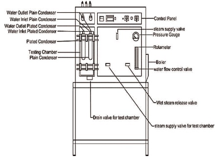
Figure 2. Parts of the Experimental Setup
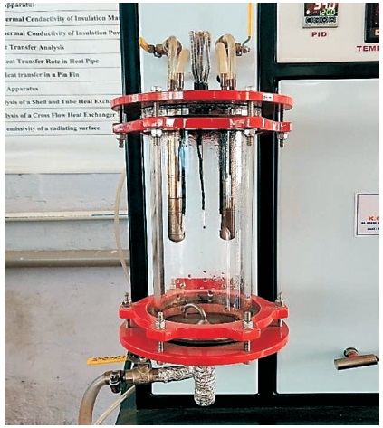
Figure 3. Test Chamber
A digital temperature controller is provided for controlling the temperature of steam. Water level indicator is provided to safe guard the heater. Condensate is measured by measuring cylinder and the stop watch. Figure 4 shows the experimental setup of dropwise and filmwise condensation.
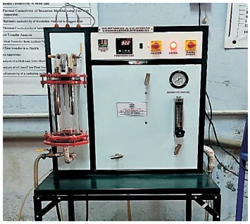
Figure 4. Experimental Setup
Tables 1-4 show the dropwise and filmwise condensation reading and results.
Fw - Flow rate of water
T - Time taken to collect V ml of condensed steam
T1, T2 – Surface temperature of plated condenser
T3, T4 – Surface temperature of plain condenser
T5 – Temperature of steam in the test chamber
T6 – Water inlet temperature
T7 – Water outlet temperature from plated condenser
T8 – Water outlet temperature from the plain condenser
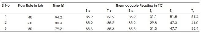
Table 1. Dropwise Condensation Reading
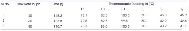
Table 2. Filmwise Condensation Reading
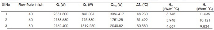
Table 3. Dropwise Condensation Result
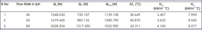
Table 4. Filmwise Condensation Result
The heat transfer coefficient is calculated both theoretically and experimentally for dropwise and filmwise condensation, respectively.
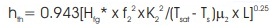
Theoretical formula for calculating heat transfer coefficient given by Nusselt is (Nag, 2011),
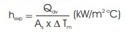
Experimental formula for calculating heat transfer coefficient is
where,
As = Heat transfer area = 2πr1 (m2)
r = Radius of the condenser tube = 0.00782 (m)
l = Length of the condenser tube = 0.175 (m)
As = 0.00865 (m2)
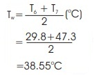
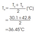
Average water temperature,
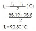
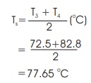
Average temperature at the surface of the condenser,
Temperature of saturated steam in test chamber, TSat
Tsat = T5 = 99.8 oC
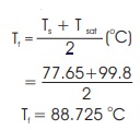
Average temperature of condensate film,
For the temperature Tw, the following properties of water is found (Rose, 2002):
f= Density of water = 995 (kg/m3)
Cp1 = Specific heat of water = 4178 (J/kg K)
And for temperature = Tsat, latent heat (Hfg) of steam is found, Hfg = 2256.9 (kJ/kg)
For film temperature Tf, the following properties are found,
f2 = Density of condensate = 964.25 (kg/m3)
Cp2 = Specific heat of condensate = 4210.75 (J/kg K)
K2 = Thermal conductivity = 0.677475 (W/m K)
µ2= Viscosity of condensate = 2.99640x10⁻⁴ (kg/m s)
Modified latent heat of steam, Hfg *
= 2256.9 + [0.68 x 4210.75 (99.8 - 90.46)]
Hfg *= 2283542.8813 (J/kg)
Mass flow rate of water,
Mass flow rate of steam condensation, Ms
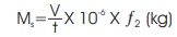
where t = time taken to collect 100 ml of condensed steam in seconds.
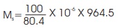
Ms =0.01658 (kg)
= 0.01658 x 4178 x (47.3 - 29.8)
= 1212.24 (W)
= 0.001199 x 2283542.8813
Q = 2738.68 (W)
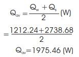
Average heat loss,
Log mean temperature difference, 
Temperature difference of surface of condenser and water inlet,∆T1
∆ T1= (Ts -T6) = 60.695 oC
Temperature difference of surface of condenser and water outlet, ∆T2,
∆T2 = (Ts - T7) = 43.195 oC
∆Tm= 54.90 oC
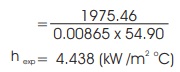
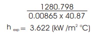
Experimental heat transfer coefficient, hexp
As=heat transfer area = 0.00865 (m2)
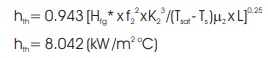
Theoretical heat transfer coefficient, hth (kW/m2)
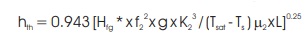
hth =10.121(kW/m2 oC)
Average water temperature,
Average temperature at the surface of the condenser, Ts
Temperature of saturated steam in test chamber, Tsat
Tsat =T5 =99.8 oC
Average temperature of condensate film,
For the temperature Tw, the following properties of water is w found,
P1 = Density of water = 997.5 (kg/m3)
Cp1= Specific heat of water = 4178 (J / kg K)
And for temperature, Tsat latent heat (Hfg) of steam is found,
Hfg = 2256.9 ( kJ/kg)
For film temperature Tf, the following properties are found,
P2= Density of condensate = 968.5 (kg/m3)
Cp2 = Specific heat of condensate = 4203.5 (J/kg K)
K2 = Thermal conductivity = 0.67455 (W/mK)
µ2= Viscosity of condensate =3.196050 x 10⁻⁴ (kg/ms)
Modified latent heat of steam, Hfg *
Hfg = Hfg [0.68 x Cp2 (Tsat - Ts )] (J/kg)
= 2256.9 + [0.68 x4203.5 (99.8-77.65)]
Hfg = 2320213.117 (J/kg),
Mass flow rate of water, Mw
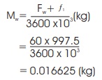
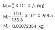
Mass flow rate of steam condensation, Ms
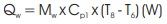
Heat loss from water, Qw = Mw x Cp1 x (T8 – T6) (W)
= 0.016625 x 4178 x (42.8 - 30.1)
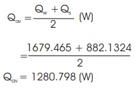
Qw = 882.1324 (W)
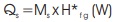
Heat loss from the steam, Qs= Ms x Hfg * (W)
= 0.00072384 x 2320213.117
Qs = 1679.465 (W)
Average heat loss,
Log mean temperature difference,
Temperature difference of surface of condenser and water inlet,∆T1
∆T1= (Ts -T6 ) = 47.55 0C
Temperature difference of surface of condenser and water outlet, ∆T2
∆ T2 = (Ts - T8) = 34.85 0C
∆Tm= 40.87 oC
Experimental heat transfer coefficient, hexp
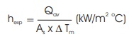
As=heat transfer area,= 0.00865 (m2)
Theoretical heat transfer coefficient, hth = (KW /m2 oC)
Percentage of error
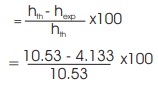
Accuracy of the plated condenser is 60.75%
Percentage of error
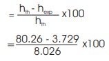
Accuracy of the plain condenser is 53.53%
The heat transfer coefficient for both dropwise and filmwise condensation is calculated by using the formula. The flow rate is varied from 40, 60, and 80 LPH, respectively and variation of parameters, such as time, heat transfer coefficient, and heat loss from the steam and water is investigated. The variation of above parameters with respect to variation, ie flow rate is recorded and compared with the help of graph, for both dropwise and filmwise condensation. The coated and uncoated in the graph indicates the dropwise and filmwise condensation, respectively. The variation of time with respect to varying flow rate is shown in Figure 5.
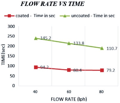
Figure 5. Variation of Time Taken to Collect 100 ml of Condensed Steam with respect to Varying Flow Rate
When the cooling water flow rate varies, the time taken to collect 100 ml of condensed steam decreases. The time taken for collection of condensed steam for dropwise condensation is less compared to filmwise condensation. This is due to low heat transfer rate in filmwise condensation, so it requires a lot of time to condense in higher heat transfer rate than filmwise condensation for both experimental and theoretical conditions. The hexp calculated is higher for dropwise condensation as expected, and the variation is shown in Figure6.
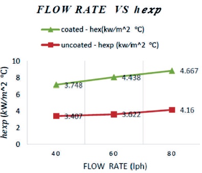
Figure 6. Variation of hexp with respect to Varying Flow Rate
In order to check the accuracy of the machine, the heat transfer coefficient is calculated theoretically with the help of Nusselt's formula. The hth value is higher than hexp value due to the presence of non-condensable gases. The variation is shown in Figure 7. The hth value calculated for dropwise condensation is much higher than filmwise condensation.
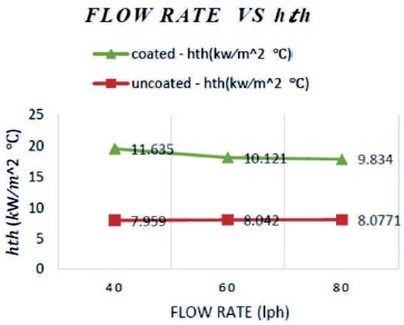
Figure 7. Variation of hth with respect to Varying Flow Rate
Figure 8 shows the increase in average heat loss from steam and water with increase in flow rate. Average heat loss in dropwise condensation is higher than filmwise condensation. Filmwise condensation shows lower heat transfer rate than dropwise condensation, which is due to the wettable nature of the condenser surface. In order to make the surface non-wettable, the condenser surface has to be specially treated.
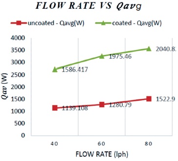
Figure 8. Variation of Qavg with respect to Varying Flow Rate
The record of observation shows that in order to achieve a better rate of condensation, the mode of condensation should be dropwise condensation. An error analysis has been made to determine the accuracy of the plated and plain condenser also percentage error calculation method has been used and it is found that the accuracy of the experimental setup is around 50-60%, due to the losses that occurred in the pipes and due to the presence of noncondensable gases in the test chamber.
An experiment for dropwise and filmwise condensation had been carried out by varying the mass flow rate. For all flow rates, the dropwise condensation results showed a good agreement. Heat transfer coefficient for both dropwise and filmwise condensation increases with increase in flow rate. Dropwise and filmwise condensation showed similar heat transfer rates, where dropwise is only slightly higher than filmwise condensation in experimental conditions due to the accuracy of the experimental setup. Hence, it is modestly concluded that for the steam and air mixture cases, the dropwise heat transfer can be reasonably approximated by the filmwise condensation heat transfer correlations. Systematic increase in heat loss were observed with increase in flow rate in both modes of condensation.
The accuracy of the experiment is checked by calculating the value of heat transfer coefficient by Nusselt's formula, where the deviation with experimental values is high and it is due to the presence of non-condensable gases in the test chamber.
We thank the Department of Mechanical Engineering, Heat Transfer Laboratory, Coimbatore institute of technology, Coimbatore, India for providing lab facility. We would also like to thank the professors and staff members who helped us during the research work.