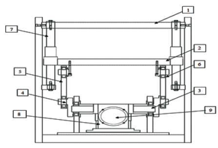
Figure 1. Forming and Cutting Die pillar station of Vacuum thermoforming Machine
The objective of this work is to design and analyze the performance of connecting rod, through a simple experimental model of Forming and Trimming Die Pillar Station of Vacuum Thermoforming Machine. A connecting rod is a machine member subjected to alternating direct compressive and tensile forces, where compressive forces are generally more in connecting rods so that it is considered for its prime safety. A parametric mathematical model of connecting rod is modeled using Pro-E Wildfire 4.0 Software and its Static Structural Analysis is carried on Ansys v-11.0 Workbench. FEA of connecting rod is done using C50 as its base material to determine its von-Misses stress, Max shear Stress, Total Deformation, and Alternating stress to cycles graph. Also, the Stiffness of connecting rod is calculated. Basically, the analysis is carried with four different element sizes such as 1 mm, 2 mm, 3 mm, and 4 mm and best element is selected indicating correct results.
In its simplest form, the Vacuum Thermoforming process essentially consists of inserting a thermoplastic sheet in a cold state into the forming clamp area, heating it to the desired temperature either with just a surface heater or with twin heaters, and then raising a mould from below. The trapped air is evacuated with the assistance of a vacuum system, and once when it is cooled, a reverse air supply is activated to release the plastic part from the mould. Today, thermoforming is a rapidly growing processing method because of the variety and relatively low cost production of various items [4]. The connecting rod used in Thermoforming machine is to transmit motion from motor through gearbox and crankshaft to bottom plate of the machine to have its motion to carry out its process of forming cum cutting off plastic sheets [7].
Thermoforming machine is used to form the plastic parts to desired shape. In Figure1, there is a top and bottom plate within which the forming cum cutting die is placed between the two plates. The Vacuum System is used to form the plastic by means of high vacuum pressure as well as high-pressure air from top and also for equal distribution of wall thickness of plastic. Before this station, there is a heating station to preheat the sheet which is to be formed, and after the heating station, forming cum cutting station is placed. Figure1 shows the experimental setup of forming cum cutting Die pillar station. The various parts of the Die pillar stations are as follows: 1)Top plate, 2)Bottom plate, 3)Shaft, 4)Crank, 5)Connecting rod, 6)Bearings, 7)Die Pillars, 8)Gear box and 9)Motor. Out of all these parts, the Connecting rod is designed which is an important part in transmitting motion.
Figure 1. Forming and Cutting Die pillar station of Vacuum thermoforming Machine
A connecting rod is a machine member which is subjected to alternating direct compressive and tensile forces, since the compressive forces are much higher than tensile forces. Therefore, the crossection of connecting rod is designed as a strut and Rankin's Formula is used. Table 1 shows the specifications of the vacuum thermoforming machine [1].
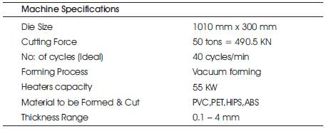
Table 1. Vacuum thermoforming Machine Specifications
Figure 2 shows the standard dimensions of an I-section[3]. Let
B= Width of I-section, mm.
H= Height of I-section, mm.
A= Area of I-section, mm2.
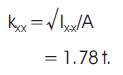
kxx = Radius of gyration of section about X-axis.
FOS = Factor of Safety.
r = Length of Crank, mm.
l = Length of connecting rod, mm.
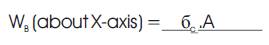
WB = Buckling Load, N.
A = Area of Section, mm2 .
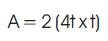
= 11 t2 , mm2 .
Moment of Inertia about X-X,
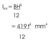
Moment of Inertia about Y-Y,
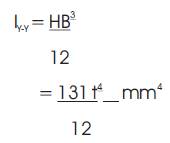
Connecting rod is considered as both the ends are hinged for buckling about the X-axis and both the ends are fixed for buckling about the Y-axis. Connecting rod should be equally strong in buckling about both axes. In order to have connecting rod equally strong in both axis, it should satisfy the following conditions, Ix-x= 4 Iy-y.
In actual practice, Ix-x is kept slightly less than 4 Iy-y . It is usually taken between 3 and 3.5 and connecting rod is designed for buckling about Ix-x .
Dividing equations (2)by (3), we have,

As the ratio is between 3 to 3.5, the I-section chosen is quite satisfactory. Basically, the force acting is 245.25 KN on each connecting rod. Generally, the Factor of safety is taken between 5 and 6. So, the selected Factor of Safety is 5.
Therefore, Bucking Load = F x FOS
= 245.25 x 5
= 1226.25 KN
Radius of gyration of section about X-axis is,

= 164 / 2
= 82 mm
Length of Connecting rod, l = 500 mm.
According to Rankin's Formula,
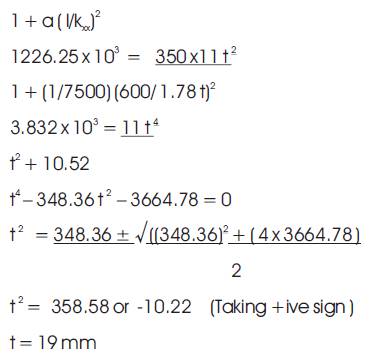
Thus, Dimensions of connecting rod are,
Thickness of flange and web of section = 19 mm

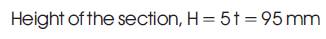


Table 2 shows the parameter values of connecting rod.
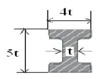
Figure 2. Standard Dimensions of I-Section
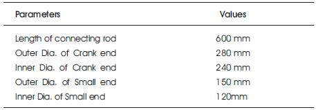
Table 2. Parameters values of connecting rod
Connecting rod is modeled on Pro-E Wildfire 4.0 software. The Mathematical Model is imported to Ansys software as shown in Figure 3.
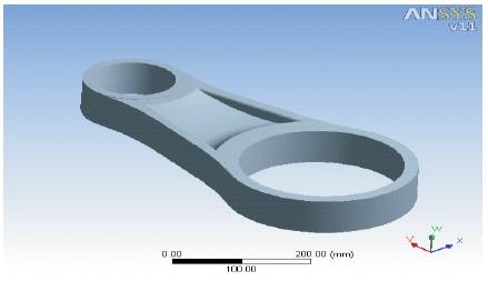
Figure 3. Mathematical Model of Connecting Rod
Open Pro-E Wildfire 4.0 software, and then enter into sketching plane section to draw the sketch of Connecting rod with the help of various sketching commands and 3D modeling commands for modeling the connecting rod. Once the Mathematical model is prepared and exported to iges format, it is imported to Ansys v 11.0 software for analysis purpose.
In this study, the connecting rod is designed for compressive yield strength. FEA of the connecting rod of allowable compressive yield strength is compared with Ansys von-mises stress. Basically, the analysis is in Static Structural Analysis module [8] .
Basically, in Ansys v 11.0 software, it automatically selects the type of mesh. In this case, tetrahedral element is selected for its analysis [6]. Figure 4 shows the meshed mathematical model of connecting rod.
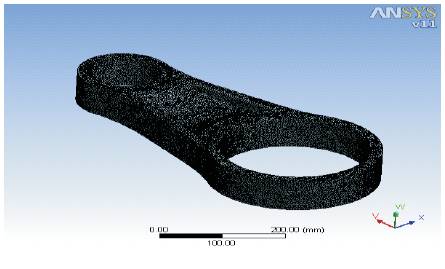
Figure 4. Meshed Mathematical model of Connecting Rod
The material properties given in below table are entered in Engineering Data with name as Structural Steel. Table 3 shows the material is properties [5].
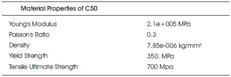
Table 3. Material Properties
Two constraints were used in this analysis.
In both the FE models one end, i.e., the crank end of the connecting rod was fixed, and the other end was not allowed to rotate about y and x- axis but free to rotate about z-axis. Also the pin end or the small end is allowed to move freely in transnational direction (in x-yz).
In FE models, no external force is acting on the big end but on the small end, 1226.3KN of compressive force is applied in the y-direction. There is no external force in the x and z direction [2].
Figure 5 shows the load and boundary conditions of connecting rod.
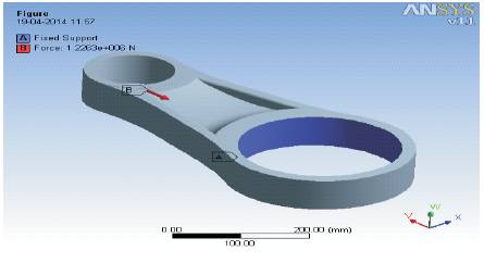
Figure 5. Load & Boundary Conditions for Connecting Rod
After all loads and displacement were applied, analysis would be the last step. Select the option called Solve. The software starts analyzing automatically, and finally solves the problem.
Once the individual attachment is done for viewing different results, select each attachment for viewing individual results.
The results are plotted for different element sizes.
Figure 6 shows the von-misses stress for element size of 1mm which is 77.59N/mm2 . Figure 7 shows the von-misses stress for element size of 2 mm which is 71.539N/mm2 . Figure 8 shows the von-misses stress for element size of 3 mm which is 63.225 N/mm2 . Figure 9 shows the von-misses stress for element size of 4 mm which is 52.978 N/mm2 .
Table 4 shows the Ansys result values. The above table indicates the results obtained with different element sizes indicating the accuracy and closeness to theoretical values (i.e. True value). It is obtained through element size of 2 mm and 3mm. But for safe design, Aansys value should be less than the given value. Due to this reason, element selected is 3 mm, and for a safe design, the required FOS is within 5 and 6.
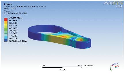
Figure 6. Von-misses Stress for Connecting rod with element size of 1 mm
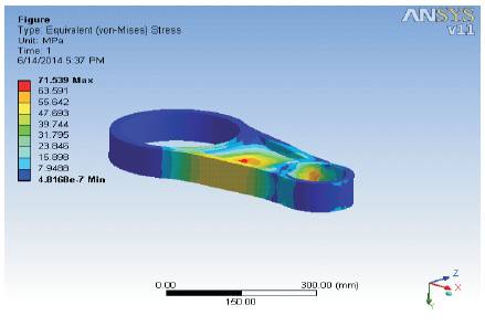
Figure 7. Von-misses Stress for Connecting rod with element size of 2 mm
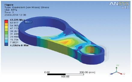
Figure 8. Von-misses Stress for Connecting rod with element size of 3 mm
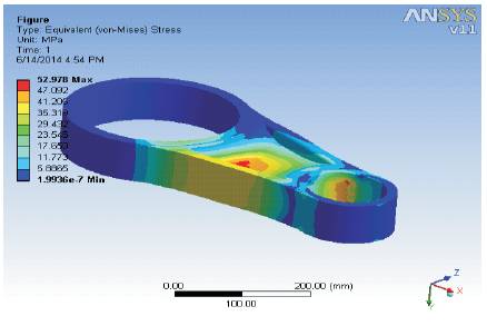
Figure 9. Von-misses Stress for Connecting rod with element size of 4 mm
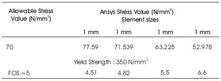
Table 4. Ansys Results values
In addition to the theoretical design, analysis was made on Ansys v 11.0 workbench in order to validate the theoretical results. It was found that, the results are almost nearer to each other. The results indicate different FOS for different element sizes. Figure 8 Indicates that, maximum stress value occurs at the small pin end, and at mid region of connecting rod.
Figure 10 shows that the max shear stress for element size of 3 mm is 35.75 N/mm2 . Figure 11 shows the deformation results for element size of 3 mm as 0.088835 mm.
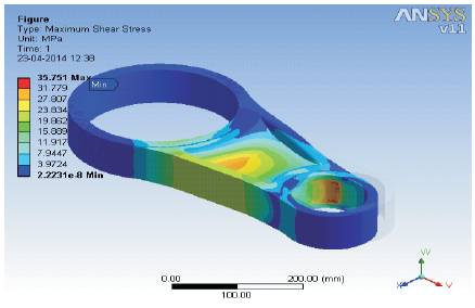
Figure 10. Max Shear stress of Connecting Rod with element size 3 mm
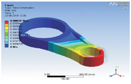
Figure 11. Deformation of Connecting Rod with element size 3 mm
Table 5 shows the Alternating stress v/s Cycles table. Figure 12 shows that the graph of Alternating Stress v/s cycles indicate the life of connecting rod. It shows that connecting rod will have a life span of about 3.16 e+6 cycles.
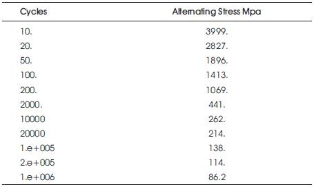
Table 5. Alternating stress v/s Cycles
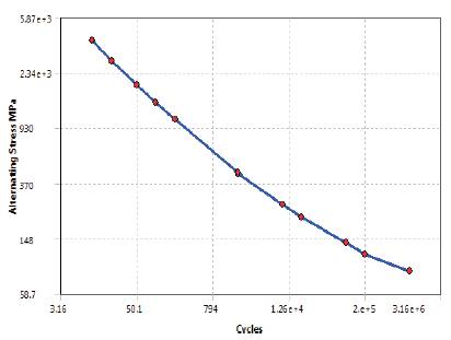
Figure 12. Alternating stresses
Results for the stiffness of connecting rod are as follows [3],
Weight of connecting rod: 29.98 kg
Deformation : 0.088835mm
Through analytical design of connecting rod, the dimensions of connecting, rod are calculated, and its mathematical model is made for its analysis in Ansys v- 11.0. The analysis was carried out with four element sizes, out of which the element size of 3mm indicates safe stress value near to allowable stress value. The Ansys von-misses stress is 63.225 N/mm2 which is near to allowable stress value. FOS is well between 5 and 6. Hence, it seems that the design of the connecting rod is safe. Connecting rod will have a life span of about 3.16 e+6 cycles, and stiffness of about 337.47 Kg/mm.