
Figure 1. Equipment for generation of ultrasonic vibrations [10]
Ultrasonic vibrations have various kinds of applications in machining operations. A large number of researchers have been involved in the investigation of ultrasonic effects in conventional machining operations. In most of the cases, they have obtained favorable effects. In this regard, this paper discusses the effects of ultrasonic vibrations, especially in EDM processes. The mechanisms which are helpful in improving the material removal include, cavitation, micro-streaming and impact forces by ultrasonic waves. One of the major challenges in EDM is to improve the sparking and flushing efficiency, which is critical in processes such as micro-EDM. Generally, it is understood that ultrasonic vibrations reduce thermal damage of the surfaces generated in EDM. Two ultrasonic parameters influencing the processes are ultrasonic amplitude and frequency of ultrasonic vibration. Several researchers have done mathematical modeling of the effects of ultrasonic vibrations in EDM. It helps in the prediction of key factors influencing the process, such as ultrasonic force required for debris evacuation and debris concentration at the inter-electrode gap.
Metal Ultrasonic vibrations are waves of frequency above the hearing range of the normal human ear and include all those vibrations of frequency of more than approximately 20,000 cycles per second. This paper gives a brief idea about the effects of ultrasonic vibrations in various machining processes including EDM and major works in the area.
In conventional machining operations such as turning, milling and drilling, vibration assisted machining is applicable over a wide range of operating conditions such as variety of i) size of parts, ii) depth of cut, iii) work materials and iv) tool materials. The major advantages are: reduced tool forces, extended tool life, improved form accuracy, improved surface finish and suppressed burr formation[1-5] . In vibration assisted ECM, the physical conditions of the gap are changed which leads to reduction of current density, increasing of uniformity of inter-electrode medium properties and localization of anodic dissolution [6-7]. In wire EDM, ultrasonic vibrations increase the cutting efficiency by 30%, improves the surface finish and reduces the surface residual tensile stresses [8]. Applying ultrasonic vibration for tapping of pure titanium metal can reduce the tapping torque [9], which is lowest at resonance frequency of vibration of the piezoelectric actuator.
In EDM, ultrasonic vibration movement of the electrode improves the high frequency pumping action in the interelectrode gap by pushing debris away and sucking new fresh dielectric, which reenergizes the gap and improves the material removal rate [10,12]. In a similar process, i.e. ultrasonic EDM in gas, during the discharge interval, the high velocity gas blows off the plasma formed by previous discharge and decreases the temperature at the interelectrode gap on the work and tool electrode, which helps in the recovery of the inter-electrode gap [13-16]. Higher efficiency achieved in using ultrasonic vibration is mainly attributed to i) better dielectric circulation, which makes the machine-debris removal easy and ii) generation of a large pressure change between electrode and work piece due to ejection of the molten material from the surface of work piece [17-20].
Under the application of ultrasonic vibration in EDM, it is observed that an alternate pressure variation is created, which increases with decrease in the discharge gap, which yields a lower MRR and vice versa. The total increase in MRR is proportional to the pressure decrement. For high amplitude to gap length ratio, effect of pressure drop on the physics of the process was found to be significant. The alternate motion of the electrode also creates turbulence and cavitation, which improves the ejection of melted metal. This also reduces material recast on the surface and microcracks, increases fatigue life of components and increases the aspect ratios of holes, over the current methods of EDM.
Many researchers have studied methods of using ultrasonic vibrations in EDM for better material removal rate [10-23], tool wear [10,18,19,and 23] and reduced heat affected zone [4]. For finishing operations, a greater MRR was obtained and the heat affected layer was lower [10]. With ultrasonic vibrations, reduction in arcing pulses also improved duty factor and frequency [11]. In an ultrasonic micro-EDM method with work piece vibration [12], experimental results showed that the efficiency increases eight times compared to micro-EDM, when the material was stainless steel. Theoretical models to determine MRR and roughness have been established [14,15]. Applying vibration motion helps in i) debris removal and to regain dielectric strength of gap [17], ii) enhancing machining of difficult-to-cut Nitinol, through strong flushing effect [18] and iii) gap servo control [19]. Higher amplitude and frequency results in shorter machining times in vibrationassisted micro-EDM [20].
Therefore, the objective of this paper is to understand the role ultrasonic vibrations play in material removal phenomena, the type of surface generated and the process efficiency. The focus of this paper is mainly on electrical discharge processes. It also involves the application of ultrasounds to machining processes like drilling and milling, to study the fundamentals and basic principles of EDM using ultrasonic vibrations, effect of ultrasonic vibrations in EDM, material removal in ultrasonic electric discharge machining and attempts to optimize ultrasonic vibration assisted ED machining. This paper has briefly covered the basic concepts, summarized recent contributions in ultrasonic assisted machining, and highlighted the importance of ultrasonic vibration EDM process. This paper is arranged as follows: The importance of ultrasonic vibration assistance in machining processes is discussed first. Further, the physics of the ultrasonic vibration assisted electrical discharge machining process and the effect of ultrasonic vibration on EDM variants are elaborated. The factors influencing the material removal in the process are then identified. This is followed by the efforts on theoretical modeling of the process.
The method involves application of vibrations to an electrode or workpiece at a frequency of 20,000 Hz or more aiming at better debris expulsion and dielectric renewal in the gap in EDM. Typical equipment for production of ultrasonic vibrations in EDM is shown (Figure 1). Under the action of ultrasonic vibrations, a to-and-fro motion corresponds to a circulation of a dielectric fluid element. This aspect involves: i) physics of ultrasonic EDM, ii) mechanism of material removal, iii) material removal phenomena in 2 newer variants of the process viz., ultrasonic micro-EDM, and ultrasonic EDM using gas.
Figure 1. Equipment for generation of ultrasonic vibrations [10]
In die sinking micro-EDM, the conventional methods of flushing are found ineffective, which restricts the material removal. Particularly, in finishing operations, when the energy requirement is small and the distance between electrodes is very short, debris removal is restricted. This facilitates introduction of ultrasonic vibrations at high frequency or amplitude having large energy and momentum, for such an application. During ultra sonic assisted EDM process, energy and momentum is transferred to the electrons in the sparking zone. Considering the ultrasonic assistance, generation of the additional action of material removal, does not require work piece to be conductive. In addition, the adverse effects due to thermal induction and chemical reactions, which usually affect the work piece, are reduced.
The role of ultrasonic vibration in this process is to push away the debris along with some dielectric liquid and suck fresh dielectric. In effect, pressure in the inter-electrode gap also varies from a maximum to minimum. This action is similar to a 'pumping action' in the inter-electrode gap which also generates turbulence.
The combined effect of the mentioned phenomena improves i) flushing effect which enhances MRR and ii) number of energetic discharges and thereby efficiency of sparking.
The acousto-electric current (combined effect of ultrasonic vibration and electrical discharge) 'I' generated in the discharge gap is given by,

where 'μ' is mobility of the charge carriers, 'Pd ' is acoustic power dissipated to charge carriers, 'L' is interaction length and 'V' is phase velocity.
A debris particle also experiences forces due to change in momentum under the action of ultrasonic vibrations: i) radiation pressure, ii) Stoke's force and iii) Bernoulli's attraction, which improves the flushing process in EDM.
The material removal rate and surface finish of a component generated using an EDM process, largely, is dependent upon the proper debris evacuation and flushing action of the dielectric fluid. These two factors play the most critical role in two processes namely micro-EDM and EDM. Therefore, these two processes have been identified as the potential areas for introduction of ultrasonic vibrations.
Effects of ultrasonic vibrations on two EDM variants viz., micro-EDM, and EDM are discussed further. Two methods are used for application of vibrations: i) vibration of tool electrode and ii) vibration of the work piece.
The important effects due to application of ultrasonic vibration are:
In EDM, debris removal and dielectric circulation are improved by applying ultrasonic vibration to the tool electrode. Using ultrasonic vibration superposed on the normal movement of tool electrode, suitable flushing conditions are achieved to yield maximum machining efficiency. In each period of vibration, when the electrode moves down, the contaminated dielectric and debris are pumped away from the inter-electrode gap (Figure 2-a).

Figure 2a. Micro-EDM set-up using ultrasonic vibrations (vibration of tool) [18].
However, in micro-EDM, when the electrode is very thin, a large vibration of the tool electrode can affect the accuracy of the process. Also, in the process, if the debris density becomes higher at certain locations in the spark gap, abnormal discharges and short circuits are formed due to a reduction in resistance, causing severe electrode wear. Similarly, in electrical discharge machining of microholes (micro-EDM), circulation of dielectric between electrode and workpiece is an important factor for improving the material removal rate [12,18]. One of the methods to overcome this problem is vibration of the workpiece, instead of tool. A set-up for ultrasonic vibration assisted micro-EDM (workpiece vibration arrangement) is shown (Figure 2- b).

Figure 2b. Set-up for micro-EDM with ultrasonic vibrations (vibration of workpiece) [12]
Stability of EDM using ultrasonic vibrations can be estimated by measuring frequency of discharge pulses and extra table movement of EDM machine in the feed direction. By providing vibrations, an increase of discharge pulse frequency was observed in micro-EDM. Also, movement of the machine table from the initially set position was reduced from 20 μm to 3 μm, with ultrasonic vibration action. One of the main reasons for short circuiting effect is the adhesion between electrode and workpiece. As a longer workpiece has lesser stiffness, to overcome a constant adhesion force, a larger deflection is necessary which increases machining time. Thus, from experimental results and observations, it was found that for high aspect ratio machining, stiffness of the workpiece which affects machining time, should also be taken into account.
Among the two techniques used (Figure 3 a-b) viz., perpendicular vibration condition (vibration direction is perpendicular to the feed direction) and parallel vibration condition (vibration direction is parallel to the feed direction), the perpendicular vibration was found to have a shorter machining time, and the shortest was observed at frequency 1 kHz and amplitude 1.5 μm.
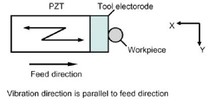
Figure 3a. Vibration direction and feed direction (a) parallel vibration

Figure 3b. Vibration direction and feed direction (b) perpendicular vibration [20]
In Ultrasonic EDM in gas (Figure 4), high pressure gas is supplied through an internal hole of a thin walled pipe and flows over the machining gap with a high velocity. The gas enhances the removal of molten and evaporated work material from the discharge gap. Ultrasonic actuation of the workpiece /tool helps in 'shaking' of the molten workpiece material not attached to the electrode and, thereby improves MRR.
Therefore, for the process to be effective, in addition to giving ultrasonic vibrations, some measures should also be taken, such as superposing of a rotation and a planetary motion to the tool.

Figure 4. Principle of Ultrasonic EDM in gas [13-16]
The effect of ultrasonic vibrations on EDM performance is identified from various performance measures such as material removal rate, tool wear, heat affected zone etc. The main ultrasonic parameters which influence EDM process considered are amplitude of vibration and frequency of vibration.
The material removal in ultrasonic-vibration assisted electric discharge machining is influenced by a number of parameters such as work material, electrode material, electrode size, applied voltage, sparking gap and ultrasonic parameters such as amplitude of ultrasonic vibration and frequency of ultrasonic vibration. The response variables which are used for evaluation of performance in electrical discharge machining are i) material removal rate, ii) Tool wear, iii) Surface finish and iv) dimensional accuracy (Figure 5).

Figure 5. Factors influencing material removal phenomena
A general machining system for vibration assisted EDM consist of a micro-feed mechanism for servo control, an XY worktable, a high-frequency pulsed power supply with monitoring circuits, vibration generation unit, signal generator, PZT power supply and an oscillograph (Figure 6).

Figure 6. Experimental system for vibration assisted EDM [19]
It is found from literature that in ultrasonically assisted EDM process, the improvement in MRR is 10% for roughing to 40% for finishing operations. Higher efficiency in finishing is attributed to the pumping action by the end of the electrode, which leads to higher material removal rate. From the experimental results in various literature, it is evident that, discharge current required for machining is lesser in ultrasonic-assisted EDM, compared to pure EDM. Also, better stability of the process is achieved by enhancing the gap with ultrasonic vibrations, by reducing the short circuits. By analyzing the effects in the sparking gap, there is a stronger stirring effect, which improves flushing of the debris thereby increasing material removal rate. The major parameters viz., ultrasonic frequency and ultrasonic amplitude, influences the EDM process in enhancing the material removal rate by reducing the machining time. Ultrasonic vibrations can also be applied to micro-EDM process, as it is possible to use wide range of values of operating variables such as discharge current and pulse duration, compared to pure EDM.
Investigations of the influence of ultrasonic vibrations on material removal rate can be classified as:
Effect on MRR/VRR
Effect on machining depth and
Effect on machining time
Effect of ultrasonic vibration parameters on MRR have been studied by a number of researchers. From the relationship between the removal rate and different machining methods, ultrasonic aided micro-EDM yields an MRR about four to eight times larger than that of micro- EDM. In micro-EDM, the circulation of dielectric and the removal of machine-debris are very difficult, especially when the aspect ratio of the hole is higher. In this case, the ultrasonic vibration of the workpiece improves the dielectric circulation and machine-debris removal and it increases the aspect ratio of hole. With ultrasonic vibrations, the MRR increases from 0.12 mm3/min to 0.58 mm3/min. MRR obtained with the effect of ultrasonic vibrations is reduced from 0.58 mm3/min to 0.23 mm3/min with increase in thickness from 0.2 mm to 0.5 mm (Figure 7a). In another investigation, variation of MRR with pulse-on time for different ultrasonic vibration amplitudes was studied. MRR increases from 1 mm3/s to 4 mm3/s, with the introduction of ultrasonic vibration amplitude of 4 μm.
Material removal rate can be expressed mathematically as

where, 'MRR' the material removal rate is mm3/s, 'M1'and 'M2' are the workpiece weight in 'g' before and after machining respectively, 'ρ' is the density of the work material and 't' is the machining time in seconds. The variation of MRR with discharge current (constant pulse-on time Ti= 1μs) for ultrasonic EDM and pure EDM have been studied (Figure 7b). In the study, tool electrode was copper to which ultrasonic vibration was supplied, and work material was cemented carbide [23]. In another study, which shows a similar trend, the variation of MRR for i) ultrasonic assisted EDM and ii) Pure EDM with pulse-on time for a constant discharge current ( I = 11 A) have been analyzed. It is generally observed that MRR increases with the introduction of ultrasonic vibrations (see Fig. 7-c).

Figure 7a-c. Effect of ultrasonic vibration on MRR a. Comparison of EDM methods [12] b. Variation with discharge current [23] and c. Effect of amplitude of vibration [13]
Ultrasonic vibration during the EDM cycle yield better MRR, more stable discharge and reduced arcing. In difficult conditions, where conventional EDM is not suitable, such as machining with large surface area and small discharge gap, ultrasonic assisted EDM is the right choice. The effect of i) ultrasonic vibrations on variation of depth machined with machining time and ii) effect of ultrasonic vibration frequency on variation of depth machined with vibration amplitude using micro-EDM are shown. (Figure 8 a-b).

Figure 8. Effect of ultrasonic vibration on MRR (effect on machined depth). a. variation of depth of hole with machining time [18]

Figure 8 Effect of ultrasonic vibration on MRR (effect on machined depth). b. Variation of depth machined with amplitude [22]
Effects of ultrasonic vibrations on machining time have been studied by a few researchers (Figure 9 a-b). The variation of machining time using ultrasonic vibrations with applied voltage during the machining of Nitinol alloy (Figure 9a), shows a decreasing trend. From the experimental investigations, it has been observed that the maximum reduction in machining time was from 42 min to 26 min. The variations of machining time with workpiece length for various frequencies and amplitudes have also been studied in a work. The effects of ultrasonic frequency on the variation of machining time with increase in workpiece length have been studied (Figure 9b). From the results as discussed above, it is understood that there is a decrease in machining time with increase in ultrasonic parameters: amplitude and frequency.

Figure 9. Effects of ultrasonic vibrations on machining time a. Variation with applied voltage [18]

Figure 9. Effects of ultrasonic vibrations on machining time b. Variation of machining time with length of workpiece (effect of frequency) [20]
Though there are many studies related to the influence of ultrasonic physical quantities such as amplitude and frequency of vibrations on MRR, there are only very few literatures discussing their effect on tool wear. It is found that application of ultrasonic vibration to the electrode increases the MRR. However, the oscillation of the vibrating unit also increases tool wear of the electrode by 10 to 15%, which is severe when graphite is used as the electrode. This is mainly due to the fact that graphite is porous, which is affected by conditions that initiate cavitation effect during vibration, which is responsible for material removal. In addition, few cavitation bubbles collapses at the electrode surface, which create shock waves. The effect is to generate heat and pitting over the surface. Thus, apart from erosion of the workpiece, tool also gets eroded, which will be severe during machining of hard materials [10,18,23].
During the machining of Nitinol alloy, which is a hard and difficult-to-cut material, the tool wear was found to increase with increase in amplitude and frequency of ultrasonic vibrations (Figure 10a). In the study, SS304 was also chosen for the micro-EDM experiments. It was also observed that electrode wear was comparatively lower for Nitinol, compared to SS304 [18]. However, when the applied voltage was increased along up to 200 V with amplitude of ultrasonic vibrations, the tool wear increased considerably. Therefore, the applied voltage influences the process along with ultrasonic vibration (Figure 10b).
Tool wear ratio is defined as the ratio of volumetric removal rate of the tool to volumetric removal rate of workpiece, Mathematically.

where,  is the volumetric removal rate of the tool and 'Vw' is the volumetric removal rate of the workpiece.
The variation of tool wear ratio with and without introducing ultrasonic vibrations, against pulse-on time for different discharge currents and against discharge current for different pulse-on times respectively is shown [23].

Figure 10a. Effect of ultrasonic vibration on (a) variation of tool wear with machining time [18]

Figure 10b. Effect of ultrasonic vibration on (b). Variation of tool wear ratio (TWR) for ultrasonic EDM and pure EDM with discharge current [23]
Heat affected zone in EDM consists of i) white layer, ii) tempered layer and iii) reheated layer. In one of the literatures, effects of ultrasonic vibrations on the heat affected layer were studied by considering the metallurgical characteristics of a surface perpendicular to the eroded surface. For steel, it was found that the white layer was continuous, regular and thicker. Also, the total heat affected layer was thinner, with a thinner tempered and reheat layer. The thickness of induced carbide layer was also small. For roughing operations, thickness was reduced from 35 μm to 30 μm and for semi-finishing from 15μm to 12 μm. [10].
From the curve for hardness variation with depth (Figure 11a), it was found that the effect was similar to that of conventional EDM, with maximum hardness at the surface. However, the heat affected layer was thinner in ultrasonic assisted EDM. Compared to conventional EDM, the maximum residual stresses in ultrasonic EDM were smaller. For finishing, the stresses were reduced from 150 MPa to 100 MPa. However, no variation in residual stresses was observed at the surface (Figure 11b). From the results, it was found that the maximum length of the surface microcracks were 6 μm for ultrasonic assisted EDM compared to conventional EDM with maximum 30 μm long crack. As micro-cracks influences fatigue, it was evident that fatigue resistance improved by inducing ultrasonic vibrations in the process.

Figure 11a-b. Effect of ultrasonic vibrations on (a) micro-hardness, (b) residual stresses [10]
By applying ultrasonic vibrations for turning, surface roughness was found to reduce up to a maximum of 77%. However, in micro-milling process such as micro-grooving using an end mill, the surface roughness was 3 times higher than using ultrasonic vibrations. In ultrasonic assisted EDM in gas, the surface roughness was found to remain unaffected due to increase in amplitude in ultrasonic assisted EDM [13-16]. In another study on die-sinking EDM, for high amplitude of 8 μm, a small increase in roughness parameters Ra(average value) and Rmax(maximum value) was observed. The increase in roughness parameters is due to increase in material removal rate. However, the surface roughness was not affected by ultrasonic amplitudes up to a value of 4μm. From the experimental results, it was evident that surface roughness increase was influenced to a large extent by the decrease in pulse on time. Therefore, an increase in roughness values from 5 to 15% was compensated by a decrease in pulse duration [10, 23].
Another experimental investigation yielded similar results. It was observed that average surface roughness increased by 10%, by employing ultrasonic vibrations (Figure12 ab). With ultrasonic vibrations, ignition delay time becomes shorter which increases the discharge energy. At the same time, in every discharge, more molten material is expelled from the discharge gap, which results in an increase in surface roughness.
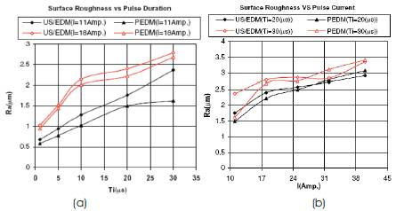
Figure 12a-b. Effect of ultrasonic vibration on average surface roughness for ultrasonic EDM and pure EDM with (a) pulse-on time and (b) discharge current [23]
In a study, microholes machined with the application of ultrasonic vibrations were examined using SEM and it was observed that through hole diameters (each of depth 2.54 mm), were larger than the respective electrode sizes [18]. This is due to the fact that at higher amplitudes, an unwanted horizontal vibration is also induced which results in profile errors (Figure 13 a,c,e).
Further, a linear damper was used to reduce vibrations in horizontal direction, which gave better profile accuracy (Figure 13 b,d,f ). However, the dimensional accuracy was not affected. The hole diameters are affected by ultrasonic vibrations with amplitude above 8μm (Table 1).

Figure 13a-f. Effect of large ultrasonic vibration amplitude on microhole profiles (a,c,e) Improvement in accuracy by using linear damper (b,d,f) [18].

Table 1. Variation in hole diameters [18].
A comparison between two micro blind holes machined by EDM process with and without vibration is shown (Figure 14 a-b). SEM photographs of blind holes machined without vibration (Figure 14a), and assisted by ultrasonic vibration at a frequency of 6 kHz and amplitude of 3 μm (Figure 14b) are shown [19].
The accuracy of diameter of machined holes was improved using vibration assisted EDM (Table 2).
From the literature based on experimental investigations, it is understood that for difficult processes such as finishing, efficiency of ultrasonic assisted EDM is high as 40%. Without vibration assistance, the debris accumulation in the narrow gap increases and affects the efficiency of the process. In ultrasonic vibration assisted EDM, less arcing leads to the stability of the process. Therefore, the process can be applied to difficult conditions like i) machining with very large surface area and ii) machining with small discharge duration.

Figure 14a-b. SEM Photographs of blind holes a) without vibration and b) with vibration [F = 6 kHz, A = 3 μm] [19]

Table 2. Improvement in dimensional accuracy using vibrations in EDM [19]
In ultrasonic vibration assisted EDM, best flushing conditions are necessary to achieve maximum efficiency. When ultrasonic vibration is superposed on normal movement of electrode, the flushing effect is enhanced. Two theoretical models of ultrasonic EDM, taking in to consideration a few factors such as i) force acting on molten metal, ii) debris concentration etc., affecting the process, as obtained from the literature is discussed. The two models are: - i) a strength model for gas EDM and ii) One dimensional fluid dynamics model.
The effect of ultrasonic vibration, considered as one of the mechanisms of material removal in ultrasonic vibrationassisted EDM for cemented carbides is explained. A strength model predicts the effect of ultrasonic vibration on a molten drop of work material by finding i) maximum inertia force, due to vibration, which helps in removal of molten material and ii) surface tension force, above which micro-crack formation occurs on the material surface. The following were the main assumptions
1. The shape of each molten liquid drop of metal is assumed to be spherical.
2. Gravity force acting on the liquid drop of metal is neglected.
3. Non-uniformity in the thermal expansion of the workpiece and thermal stresses caused are not considered.
The strength model of a molten drop (Figure 15), can be considered as a part of a sphere, where fc is inertia force aroused by ultrasonic vibrating and fg is gravity, which is very small compared to fc that can be neglected and fz is surface tension of liquid drops.
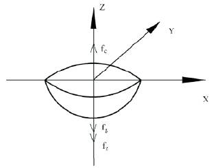
Figure 15. Strength model of molten drops [16]
The model formulation involved the following steps:
1) From the displacement between assumed ultrasonic vibration generation point to the liquid drop, y(t), speed and acceleration of the drop is determined.
2) The maximum acceleration of the drop is found out.
3) Maximum inertia force acting on the liquid drop due to ultrasonic vibration of the tool is determined.
4) Surface tension of the liquid drop is found out.
The displacement between a liquid drop and the ultrasonic vibration node can be expressed as a formula during ultrasonic vibration assisted electrical discharge machining in a gaseous medium:

where 'f' is the frequency of ultrasonic vibration and 'A' is the amplitude of ultrasonic vibration.
Finally, the maximum inertia force of the drop is

The surface tension of the liquid drops can be found out by the expression,

where, M is a coefficient, ρ is the density of the metal, Tm is the melting point of the metal, C1 is adjusting coefficient of density and C2 is adjustment coefficient of melting point. It was understood that the melting liquid drops can be easily expelled with the effect of inertia force generated by ultrasonic vibrating. When the surface tension intensity is above the thermal stress of the material, micro-cracks are found to form on the surface of the material.
Another theoretical model (one-dimensional fluid dynamics model) was established based on a physical model (Figure 16) to analyze the stirring effect by using ultrasonic vibrations [18]. The model predicts the effect of ultrasonic vibration on the concentration of debris at the bottom of a hole machined using EDM. The following were the main assumptions:
1) Ultrasonic vibration of the electrode of diameter 'd' only generates a longitudinal wave along the axis of the electrode.
2) The gap between electrode and work material 'δ' is small enough for the fluid motion to satisfy the wave condition

where, ‘s' is the fluid displacement,'t' the time variable and cw the wave speed.
3) The debris is located at the bottom of the hole with a concentration of 80% at the beginning and during computation, there is no increase of debris. ( ie., S=0 )
Model formulation is as follows:
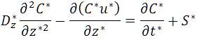
The transport of debris along z axis inside the hole should satisfy the following condition:-

where C is the debris concentration, u the fluid velocity, Dz the diffusion coefficient and S the source or sink flux. Fluid displacement and fluid velocity was found out. To non dimensionalize the model, the hole depth, H, and the time period of vibration, T, are used as the reference length and time, respectively.
The final non-dimensional equations were

The movements of the dielectric fluid and the debris are governed by the equations (9) and (10), which are influenced by the machining conditions viz., d,δ,H,A0 and ω. It is understood that, this model was found to agree well with the experimental results (Figure 17).

Figure 16. Flushing model for ultrasonic vibration assisted micro-EDM [18].

Figure 17. Effect of ultrasonic amplitude on debris concentration at the bottom of the hole [19].
Introduction of ultrasonic vibration to EDM improves its machining performance on materials which are even 'difficult-to-machine'. Among the newer techniques to improve the efficiency of sparking in novel processes such as micro-EDM, superposing of ultrasonic vibrations has generated several beneficial effects such as improvement in machining efficiency, thinner heat affected layer etc. From the literature, the result of experimental investigations shows that ultrasonic assisted EDM is a very efficient method for machining of a variety of materials. In conventional machining operations such as drilling and end milling, by the application of ultrasonic vibrations, generally it is observed that surface roughness reduces to a large extent (up to 77%). However, from the results of few investigations on EDM, it was found that the tool wear and surface roughness also increases with the use of ultrasonic vibrations