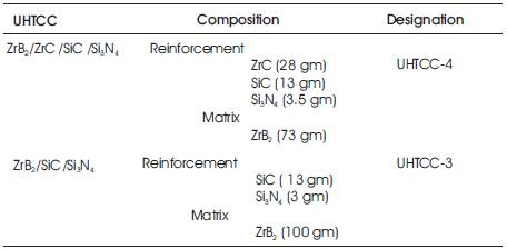
Table 1. Composition of Two Ultra high Temperature Ceramic Composite (UHTCC)
The objective of the work is to find out microstructure and properties of two zirconium diboride based ceramic composites which were obtained from fine commercial zirconium diboride powders and the addition of zirconium carbide, Silicon carbide, Silicon nitride as secondary phases and correlation between microstructure-thermo mechanical properties of two Ultra High Temperature Ceramic Composites (UHTCC) based upon the different secondary phases composition. After that characterization, the influence of composition in microstructure on elevated temperature behavior of zirconium diboride based ultra high temperature ceramic composites are analysed. Micro -structural analyses by Optical and SEM showed oxidation-induced surface modifications of ZrB2/SiC materials with oxide layers composed of silica, boron and zirconia (at higher temperature). These composites were prepared from zirconium diboride, zirconium carbide, Silicon carbide and Silicon nitride powders by ball milling and hot pressing. These two UHTCCs were fabricated by hot pressing into 25 mm diameter and 4 mm thickness discs. The measurement of the mechanical properties of two ceramic composite were done by pulse-echo ultrasonic testing. Indentation water quenched method was used for measuring thermal stresses in UHTCCs during characterizing thermo mechanical properties and thermal shock behavior.
Hypersonic flows have been associated with the re-entry of orbiting and other high altitude bodies in the atmosphere. Hypersonic flow is the presence of an interaction between the oblique shock wave generated at the leading edge of the body and thermal boundary layer on the surface of the body. Ultra High Temperature Ceramics Composite (UHTCC) are being investiged as a possible approach to overcome all deficiencies. Transition metal diborides such as ZrB2 and HfB2 are commonly referred to as Ultra High-Temperature Ceramics (UHTC) for their melting temperatures above than 3300 K. Applications are also found in the aerospace industry, hypersonic re -entry vehicles, leading edges, nose caps, rocket nozzle inserts and air-augmented propulsion system components. Objective of the work is to characterize the promising materials (UHTCCS) for industrial sectors, like foundry or refractory industries as furnace application or heat resistance application.
Ultra-High Temperature Ceramics began with the development of diboride ceramic matrix composites in the late 1960s by the U.S. Air Force. One [2] provides a comprehensive review of the work accomplished in the 1960's and early 1970's. from U.S. Air Force contracts to Manlabs, Inc. In the late 1960's and early 1970's, Kaufman and Clougherty conducted an extensive study of the properties of what were the best HfB2 and ZrB2 available at that time. Additions of silicon carbide are used to enhance oxidation resistance and limit diboride grain growth. Carbon is also sometimes used as an additive to enhance thermal stress resistance. The diborides that the Air Force considered when developing these composites were zirconium and hafnium because of their thermo-chemical stability and oxidation resistance at high temperatures [1]. Previous studies on diboride compounds gave a good working description of their chemical, physical and thermodynamic properties in regard to their response to high temperature oxidizing environments. Further tests showed that the addition of SiC to the ZrB2 and HfB2 composites would further improve their oxidation characteristics while not being detrimental to the high temperature stability of these materials [3]. Oxide formation of ZrB2 or HfB2 is dependent on ZrO2 or HfO2.Chemistry point of view; ZrO2 and HfO2 are not good choices for a protective oxide scale. In addition, the volatile oxidation products cause the formation of a porous, permeable oxide scale. Another issue with ZrO2 and HfO2 scales is their phase instability. At high temperatures, ZrO2 and HfO2 are tetragonal. Upon cooling to room temperature they transform to the monoclinic structure with an attendant volume expansion. This phase transformation, coupled with their high thermal expansion coefficient and low thermal conductivity, can easily lead to cracking and spalling under thermal transient conditions [4]. Due to the high melting point and high vapour pressure of the constituents, the sintering of ZrB2 powders is rather difficult. Relatively high densities are achieved only by pressure-assisted sintering procedures at temperatures higher than 1900°C, i.e. temperatures exceeding 70% of the absolute melting temperature. The properties of the dense materials then become strictly dependent on the starting powders and processing parameters as they determine micro structural features such as grain size, volume and chemistry of the secondary phases, etc. ZrB2-based materials for better properties like toughness, stress corrosion cracking and high temperature oxidation, many applications of these materials require the addition of a second reinforcing phase to form complex structures or alloying elements to form solid solutions [5]. From the mechanical point of view the composite materials generally performed better than the monolithic ZrB2 ceramic at room temperature, the fracture toughness and the flexural strength were almost doubled. The high temperature strength behavior was different for the monolithic and the composite materials due to the different grain boundary phase characteristics. Oxidation behavior of ZrB2 powders below 800°C was reported recently by Zheng et al [6 & 7]. The objective of the work is to find out microstructure and properties of two ZrB2-based ceramic composites which were obtained from fine commercial ZrB2 powders and the addition of ZrC, SiC, Si3N4 as secondary phases and correlation between microstructure-thermo mechanical properties of two Ultra High Temperature Ceramic composites (UHTCC) based upon the different secondary phases composition.
The investigated materials were fabricated by hot pressing. The hot pressed products were discs of 25mm diameter and 4mm thickness. Details of compositions, fabrications and designations are given in Table 1.
Details of Physical-Thermo-mechanical properties of ultra-high temperature ceramic materials (reinforcement and matrix) are given below in the Table 2 (as taken from [8]).
Table 1. Composition of Two Ultra high Temperature Ceramic Composite (UHTCC)
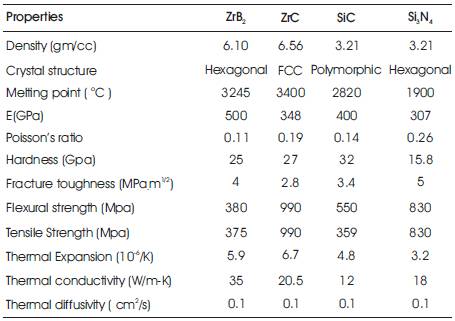
Table 2. Physical-Thermo-Mechanical Properties of Ultra- High Temperature Ceramic Materials
Nondestructive test methods include penetrant testing, Eddy current testing, magnetic evaluation, X-ray evaluation and ultrasonic testing. Ultrasonic testing can be used not only in detecting cracks, holes and inclusions, but also in evaluating material characteristics such as density, texture and mechanical properties. Objective of the work is to characterize the promising materials (UHTCCS) for high thermal resistance application.
Determination of density is based on the Archimedes principle i.e. density is the ratio of weight in air to the weight loss. Determination of density is based on the Archimedes principle as given in Table 3.
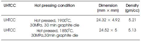
Table 3. Physical Properties of Two UHTCC
The general high temperature behavior of the ZrB2-based ceramic composites can be mostly related to the characteristics of the grain boundary phase of these materials. After surface preparation, the specimens were examined under the optical microscope with the magnifications of x100 and x200; etching in 10ml glycerin+10 ml HNO3 + 10 ml HCl + 0.1 ml HF. Polished cross sections of the hot-pressed samples were examined to characterize their micro structures. Sample images were collected and analyzed for grain sizes, and phase areas. Each image was selected to be representative of the bulk Micro structure.
Hardness is done by Vickers indentation method and load applied is 30 kg and 50 kg. Elastic modulus is related to the inter-atomic forces and hence indicates maximum attainable strength. There exists a direct mathematical relationship between elastic modulus and ultrasonic longitudinal (VL) and shear velocity (VT). Experimental results showed that the velocity of an ultrasonic sound wave in ceramic composites decreased proportionally with increasing porosity. Young's modulus and Poisson's ratio calculated from the longitudinal and transverse ultrasonic velocities were found to be dependent on porosity [9]. There are various relationships with different parameter in mechanical properties.
These relationships are as follows:
Young's Modulus E = ρ.VT2. (3VL2 – 4VT2) / (VL2 – VT2), Shear Modulus G = ρ. Vt2,
Bulk Modulus B = ρ. (VL2 – 4. (VT2 ) / 3), Poisson's Ratio υ = (VL2 – 2. VT2) / (2.VL2 –2. Vt2),
Fracture toughness KC is given by: KC = √E.Gc.
E is the Young's Modulus; Gc is the strain energy release factor.
Fracture toughness measurement is done with equation which is given below:
Evans & Charless: 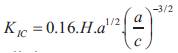 Where H=hardness in GPa, a=crack length in µm.
Niihar: KIC = 0.0309(E/H)0.4 (P/c3/2) Where P=load in Kg, c in µm, E = Young's Modulus in Gpa
Anstis:KIC = 0.01± 0.004)(E/H)1/2 (P/c3/2) Laugier:KIC = 0.010.(E/H)2/3 (P/c3/2)
The accuracy of any ultrasonic measurement is only as good as the accuracy and care with which the gage has been calibrated. All quality ultrasonic gages provide a method for calibrating for the sound velocity and zero offset appropriate for the application at hand. It is essential that this calibration be performed and periodically checked in accordance with the manufacturer's instructions. Sound velocity must always be set with respect to the material being measured. Zero offset is usually related to the type of transducer, transducer cable length and mode of measurement being used. To measure the velocities of longitudinal waves, a normal incidence transducer of 5 and 10 MHZ was used. The EPOCH4 ultrasonic flaw detector (as shown in Figure 1) with its high voltage pulse, the quality of its square pulse and selectable narrowband filters is the instrument of choice for this technique. With the values of materials' densities and ultrasonic velocities of longitudinal and transverse waves, the elastic modulus was calculated based on the ASTM E 494-1995 norm (Measuring Ultrasonic Velocity in Materials) using the equation. After the measurements of the longitudinal and transversal wave ultrasonic velocities, the elastic modulus of each sample was calculated, considering the ASTM E 494-95 norm. According to the ASTM E-494-05 norm, the results for the elastic modulus obtained by ultrasound testing have an error around 1% in comparison to the values obtained by mechanical testing. Elastic modulus is related to the inter-atomic forces and hence indicates maximum attainable strength. There exists a direct mathematical relationship between elastic modulus and ultrasonic longitudinal and shear velocity.
Figure 1. EPOCH4 Ultrasonic Flaw Detector
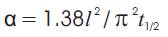
Thermal diffusivity and conductivity: The understanding of two thermal properties (diffusivity and conductivity) is important in order to take full advantage of these materials in high temperature applications. Analytical studies have shown that the behavior of these two properties is a function of the material type, volume percentages of the constituents, phase distribution, direction of heat flow, types of fibers, angles of fibers and basic properties of the constituent materials. Fabrication methods, coating applications, impurities, degree of dissimilar component contact, interfacial thermal barriers, and defects have all contributed to the difficulties in predicting the thermal behavior of these composites. In most cases, these factors lead to a lowering of the thermal conductivity of the composite. A variation of the longitudinal transient heat flow method is the primary method that is used to obtain diffusivity data. Commonly referred to as the flash method, this method was developed by Parker, Jenkins, Butler and Abbott in 1961. The flash method has advantages over other methods and is a good choice for sample analysis performed at high temperature. Parker et al [10] found that the flash method eliminated the problem of thermal contact resistance, and heat losses were minimized because the measurement time period was so short that very little cooling took place. Additionally, the back surface temperature did not begin to change during the heating pulse. Thus, the sample can be treated as an infinite slab despite being very thin. For diffusivity measurements, the amount of energy absorbed on the front surface does not have to be known. This value of the energy absorbed is only needed to determine specific heat or conductivity values via the flash method. The following equation is used to calculate diffusivity by the flash method, where “α” is diffusivity, “l” is thickness and “t1/2 ” the time when the back of the sample reaches half its maximum temperature.
Samples are often coated to darken their surface. This prevents irradiation of the back of the sample, increases the amount of energy absorbed during the flash pulse, and ensures that the absorptivity of all samples is identical. All references listed in this paper used the flash method for composite diffusivity or conductivity measurements. Diffusivity is related to thermal conductivity by the following equation, K =α.ρ.Cp
Where K is thermal conductivity, α is diffusivity, ρ is density, and Cp is specific heat. Parker et al. took heat losses via radiation and convection into consideration when they used the flash method. R.C. Heckman in 1972 published a paper which further discussed radiant and convective heat losses from the sample face. Thermal conductivity is a measure of the steady state heat transfer rate. It can be combined with the density and the specific heat to determine the thermal diffusivity. The thermal diffusivities of the UHTCs decreased with increasing temperature. In all samples, the thermal diffusivity exhibited a monotonically decreasing trend, which was the behavior expected in this temperature range. The limited numbers of data points were fit well by an equation of the form A + BT + CT -1
Thermal shock behavior of the materials were investigated by different techniques
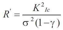
Thermal Shock Resistance is an ability of material to withstand sharp changes in temperature. If a ceramic material is rapidly cooled, its surface reaches the temperature of cooling environment and tends to contract (thermal contraction). Since the interior regions of the material are still hot, thermal contraction of the skin surface is impossible. This leads to formation of tensile stress (thermal stress) in the skin. Such thermal stresses may cause cracks and consequent failure. Thermal shock resistance of a material may be estimated in accordance to the formula:
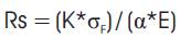
Where, Rs – thermal shock resistance; K - thermal conductivity;
σF – flexural strength, α-coefficient of thermal expansion (CTE); E – modulus of elasticity
Measured the thermal shock parameters (R, R', R", R'", and R"") for conventional ZrB2 based composites that were prepared by hot pressing. Thermal shock parameters (R, R', R", R'", and R"") were calculated using Equation,
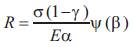
Where σ is strength, v is Poisson's ratio, E is Young's modulus, ∞ is coefficient of thermal expansion, and ψ (β) is a stress reduction factor. The stress reduction factor, which is a function of the Biot modulus (β) is used to correlate the calculated behavior (assumes instantaneous heat transfer) to measured values, where heat transfer is not instantaneous.
Thermal shock parameters were characterized by two parameters.
Thermal shock strength (R), R = σ(1-γ) / αE = ΔT , R = Kσ(1-γ) / Eα = Δtc
The conditions for crack initiation and propagation have been extensively analyzed by Hasselman et al [11 & 12]. Due to covalent bonding Si-based ceramics such as silicon carbide and silicon nitride exhibits low thermal expansion coefficient and high thermal conductivity, and therefore a high resistance to thermal shock. Investigation of the behavior of Vickers indentation cracks under quenching condition has raised interest due to their simplicity to estimate thermal shock resistance. The advantage of indentation-quench method developed by Andersson and Rowcliffe [13] is easy preparation of experimental samples and small number of samples required for a series of measurements at different temperatures. The indented specimens were heated at predetermined temperatures in air. The temperature was held at a specified maximum for 20 min, and then specimens were quenched in water at room temperature. The lengths of radial crack, 2a, were measured by optical microscope. The procedure was repeated at increasing quench temperatures T, up to the critical value Tc at which radial crack becomes unstable and the specimen failed. The thermal shock resistance was observed by measuring the retention of the flexural strength after thermal shock test. Rapid decrease in temperature, the surface of the component is placed under tension and the interior under compression. If the tensile stress developed on the surface exceeds the strength of the material, the cracks are generated, leading to a rapid drop in flexural strength. Furthermore, with the increase in temperature difference, more extensive crack interactions were observed. The increase in apparent stress after 1st drop implies the mid plane shears stress after thermal shock. The specimens shocked with the highest temperature difference had the most extensive crack propagation. The conditions for crack initiation and propagation have been extensively analysed by Hasselman et al. When composite materials are subjected to the rapid temperature changes crack nucleation and/or propagation occurs resulting in loss of strength and material degradation. The formation of cracks decreases the velocity of ultrasonic pulses traveling in the composites because it depends on the density and elastic properties of the material. By determining the bulk density, the Poisson's ratio and ultrasonic velocity of composite material it is possible to calculate the dynamic modulus of elasticity using the following equation
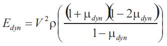
The following expression for the strength degradation, based on decrease in ultrasonic velocity was used.
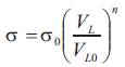
Where, σ0 is compressive strength before exposure of the material to the thermal shock testing. VL is longitudinal or transversal (VT) ultrasonic velocity after testing and V L0 is longitudinal (or transversal VT0 ) ultrasonic velocity before testing and n material constant (n = 0.488).
Polished cross sections of the hot-pressed samples were examined to characterize their microstructures. Sample images were collected and analyzed for grain sizes, and phase areas. Measurements of the grain sizes gave information on grain growth, agglomeration, and the effect of silicon carbide on microstructures. The relation between UHTCC microstructures and properties was determined using advanced electron microscopic analysis. The SiC /Si3N4 phase and the pores were indistinguishable using the image analysis software with the Scanning Electron Microscope (SEM) images as shown in Figure 3. The SiC /Si3N4 contents and porosity were measured from the micrographs and compared to the SiC & Si3N4 additions and the porosity (as measured by the Archimedes method) for each sample. Optical image analysis (as shown in Figure 2) of the diboride UHTCC-3 shows small regions at the grain boundaries with compositions that are probably derived from impurities present in the starting powders.
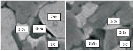
Figure 2. Optical Microstructure of ZrB2-SiC-Si3N4 Ceramic Composite (UHTCC-3)
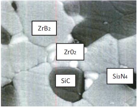
Figure 3. SEM of ZrB2-SiC-Si3N4 Ceramic Composite (UHTCC-3)
The hot pressed specimens were generally free of internal defects. With experience we were able to achieve room temperature strengths of 400 – 500 MPa and fracture toughness values of 5 – 6 MPa-m½. Weaker material either had large internal process flaws such as pore or agglomerates, or the test bars had machining flaws. The accuracy of any ultrasonic measurement is only as good as the accuracy and care with which the gage has been calibrated. All quality ultrasonic gages provide a method for calibrating for the sound velocity and zero offset appropriate for the application at hand. It is essential that this calibration be performed and periodically checked in accordance with the manufacturer's instructions. Sound velocity must always be set with respect to the material being measured. Zero offset is usually related to the type of transducer, transducer cable length and mode of measurement being used. Result of different sound velocity by ultrasonic testing is given in Table 4.
Result of mechanical properties (like hardness, flexural strength and fracture toughness) are given in Table 5 (Taking E=452 GPa & 387 Gpa).
From the mechanical point of view the composite materials generally performed better than the monolithic ZrB2 ceramic at room temperature, the fracture toughness and the flexural strength were almost doubled.
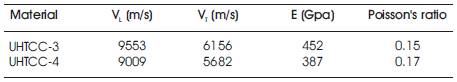
Table 4. Ultrasonic Sound Velocity for Mechanical Properties Calculation
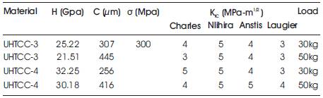
Table 5. Mechanical Properties of Two UHTCC
Thermal conductivity is a measure of the steady state heat transfer rate. Thermal conductivity decreases with increase in temperature as shown in Table 6. It can be combined with the density and the specific heat to determine the thermal diffusivity. Alternatively, the thermal conductivity can be calculated from the thermal diffusivity and specific heat, as was done in this work as shown in Tables 7 & 9. Based on the ASTM standards for each measurement, thermal diffusivity is estimated to be accurate within 5%, density to better than 1%. The thermal diffusivities were affected by the porosity, the temperature, and the SiC content. The estimated error was also found to vary with temperature. At the higher temperatures some surface oxidation occurred that might have affected the measurements. The thermal diffusivities of the UHTCCs decreased with increasing temperature as shown in Table 7. In all samples the thermal diffusivity exhibited a monotonically decreasing trend, which was the behavior expected in this temperature range as shown in Table 8. Other thermal properties (like Coefficient of thermal expansion and thermal shock parameters) of two UHTCCs are given below in Tables 10 to 11.
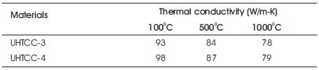
Table 6. Thermal Conductivity of Two UHTCC
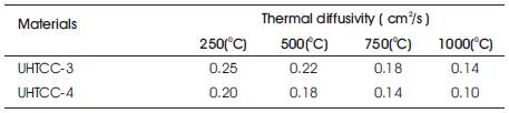
Table 7. Thermal Diffusivity of Two UHTCC
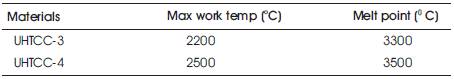
Table 8. Different Temperature of Two UHTCC
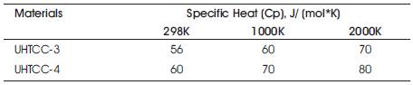
Table 9. Specific Heat of Two UHTCC
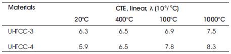
Table 10. Coefficient of Thermal Expansion for Two UHTCC
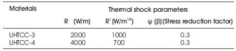
Table 11. Thermal Shock Parameters of Two UHTCC
Within uniform microstructure, it is seen that matrix cracking due to thermal expansion mismatch between the fibers and the matrix constituents is an area of concern. Flexural strength was close to expected values based on beam theory and the rule of mixtures with no matrix contribution. Zirconia samples were used to show the influence phase transformation from monoclinic to tetragonal. The study of residual stresses revealed that the magnitude of the tensile stresses in the zirconium diboride matrix was relatively insensitive to the size of the silicon carbide particulates, but the special extent of the stresses was strongly linked to particle size and shape. The decrease in young's modulus may be an indication of damage accumulation in the specimens as quench temperature increased. Finer microstructure of composite has also the negative influence on the indentation thermal shock resistance. Silicon nitride enhanced toughening mechanisms to increase the thermal shock resistance. Together with higher strength, fracture toughness and lower Young's modulus, it results in better thermal Shock resistance.
This part of the work was done within sponsored project works sponsored by DRDL, Hyderabad, in IIT, kharagpur, Dept of Metallurgical and Materials Engineering as a Senior Research Fellow under Dr. R. Mitra and Dr. K .K .Roy.