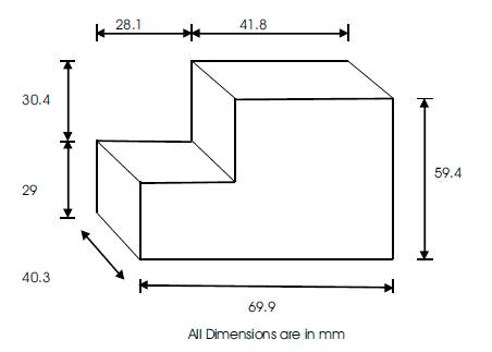
Figure 1. Expandable Polystyrene Pattern
In the present scenario, the dimensional accuracy and surface roughness of casted complex shape products have become a critical issue to reduce machining cost in terms of time, price and scrap materials. So, different types of casting processes have been introduced. One of the important casting process is Investment Casting Process with Expandable Polystyrene Pattern, instead of wax pattern. In this casting process, the shell is made by decomposition of Expandable Polystyrene pattern with the application of heat. During the foam removal process, several problems have been created such as bending, expansion, distending and crack of the shell. In this paper, Zirconium Flour and Mullite sand (Aluminium-Silicate) have been introduced as coating materials with different ratio, with binder as Sodium Silicate and Potassium Silicate. Twelve samples have been prepared and the densities and viscosities of each sample are calculated. Twelve shells are also generated. For selection of best shell material composition, Analytical Hierarchy Process (AHP) is used. Sample 7 has the best result. Also, Potassium Silicate is found to be better than Sodium Silicate as binder, to reduce distending of shell, cracks, etc. and to increase surface finish and strength to weight ratio of shell.
Aluminum alloy castings are widely used in the automobile and aerospace industries, and are replacing heavy forged steel and cast. Producing defect free Aluminium castings become more important. Investment casting is one of the oldest casting process. It is used for producing better dimensional accuracy of complex shape products [1] , [2]. Another important process is Evaporative Pattern Casting (EPC). In this process Expandable polystyrene pattern is used. It is a cavity less and binder less process. There is no need to create the core. With the help of this process, we can fabricate the cylinder head [3].
Chen et al. (2011) fabricated the ceramic moulds with zirconia primary coat for investment casting of gamma Titanium Aluminide based alloys (TiAl alloys). The microstructures and fracture strength of ceramic moulds were characterized. The fracture strength and surface roughness of the ceramic moulds with zirconia primary coat were sufficient for the TiAl investment casting. TiAl castings produced by the ceramic moulds exhibited an average surface roughness (Ra) of 6 μm [4]. Huang et al, (2007) studied the process of investment casting with ice patterns. The dimensional accuracy and surface roughness of metal castings from ice patterns were measured compared with other rapid prototyping patterns. It was observed that the ice pattern has a contracted cast part while the Stereo Lithography (SLA) pattern has an expanded cast part [5]. Behm et. al. (2003) examined the effect of process parameters like pouring temperature, presence of pattern coating, and pattern surface area to volume ratio on emission characteristics [3].
The polystyrene used for Evaporative Pattern Casting (EPC) process consists of 92% C and 8% H. The C6H5 benzene ring in polystyrene is relatively stable and –CH= CH2- chain tends to decompose first. The benzene ring remains in liquid phase and reacts with melt causing casting defects. The co-polymer of Polystyrene and Poly Methyl Meth acrylate (PMMA) was developed to reduce the carbon related defects in ferrous castings. PMMA decomposes mostly into gas phase, like 80% at 700°C while polystyrene only 40% at 700°C [6] , [8] . Barron [1965] explained that smooth surface of the pattern can be obtained by use of small, light weight polystyrene beads and thin walled low density pattern [9]. Kumar et al. [2007] studied density and bead size of polystyrene pattern in evaporative pattern casting process. A low density pattern is required to minimize the amount of gas evolved during vaporization of the pattern. Since, the gas must permeate through the coating, sand and vent into the atmosphere. If the gas forms faster than it can vent, a defective casting will result. Gas formation is a function of pattern density and metal pour temperature. If pattern density is increased, more gas is formed at a constant pour temperature. If pattern density is held constant and pour temperature is increased, more gas is formed since the polystyrene molecules will break down into more basic molecules at the higher temperature [10]. Ac´imovic-Pavlovic et al. (2011) studied the characteristic of cordierite ceramics. It has low thermal expansion coefficient (2.1–2.5 * 10-6/ K). There is reduced risk of coating cracking with temperature changes during the pouring of liquid metal, formation and crystallization of castings. Taking into consideration that cordierite has high refractoriness; its application should be extended even to the alloys casted at temperatures up to 1200° C [11].
Kumar et al. (2004) performed coating analysis using filler materials siliminite, quartz, and aluminum silicate in combination with zircon flour and binder for considering cost economy. In addition, zircon flour with aluminum silicate was found to be low dielectric constant, high density, high viscosity, and pH value nearer to neutral refractory [12]. Mullite is an attractive, high-temperature, structural material due to its excellent strength and creep resistance at high temperature, good thermal stability, low thermal conductivity, as well as its chemical inertness [13] , [14] . Kumar et al. (2008) studied the different coating materials like zircon flour, flyash and bentonite with different ratio. The optimum combination for refractory filler was observed as zircon flour (80% by weight), flyash (16% by weight) and bentonite (4% by weight). The effect of temperature on this sample was found minimum with a loss of material 1.54%. It has the combination of small and large grain size particles. Particles of different grain size contribute uniform, continuous coating on pattern due to better packing between the particles [15]. Tanaka et al. (2001) evaluated the zircon material properties used- thermal conductivity of 2.44 W/m °C, density of 3600 kg/m3, and temperature dependent heat capacity and emissivity for the temperature range from 400 to 800 °C [16] .
A binding agent for the coating was chosen with regard to the size and shape of the refractory filler particles in order to enable connection between the particles and to provide good adhesion of refractory particles to the observed surface of polymer pattern. Water was used as a liquid solvent. The optimal density of refractory coating was 2000 kg/m3 [17-18] . Molibog and Littleton (2001) examined porosity in Al alloy castings produced by lost foam process. This is due to the pyrolysis of the polystyrene foam pattern during pouring, which results in detrimental effect in mechanical property. It can also lead to a lack of pressure tightness. Internal pores are caused by the liquid polymer trapped within the liquid metal. The metal solidifies before the liquid polystyrene foam escapes to the metal-coating interface. As the pyrolysis of the liquid polystyrene foam continues, a bubble of gaseous decomposition product is trapped in the partly frozen casting. The slow solidification rate promotes the formation of pin holes, and relative weakness of the thermal gradients can cause micro-shrinkage if the outline of the part complicates feeding in the lost foam casting [19].
Based on literature review, Evaporative pattern casting is facing problem of pin hole, ash content in casting etc. In investment casting process, these defects can be reduced. Generally, wax pattern is used in investment casting. But due to low softening point, the change in shape of wax pattern takes place. Another problem is to handle the big and complex shapes of wax pattern. So there is a great opportunity in investment casting to use Expandable Polystyrene pattern, instead of wax pattern. The different combinations of coating materials (zircon and aluminium silicate with sodium silicate or potassium silicate binder) have been examined in the terms of density, viscosity and the nature of shell. Also, optimized by using Analytical Hierarchy Process (AHP).
In this paper, Zircon flour and Mullite sand are used as coating materials, in different ratio and composition. Sodium silicate and potassium silicate are used as binder. Since, the zircon flour is eight times costlier than mullite sand, composition of powder has been selected in such a way that the total casting cost is reduced. The following combinations of coating materials have been selected for primary coating.
Sample: 1 – Zircon (0 %) + Mullite (40 %) + Sodium Silicate (60%)
Sample: 2 – Zircon (5 %) + Mullite (35 %) + Sodium Silicate (60%)
Sample: 3 – Zircon (10 %) + Mullite (30 %) + Sodium Silicate (60%)
Sample: 4 – Zircon (15 %) + Mullite (25 %) + Sodium Silicate (60%)
Sample: 5 – Zircon (20 %) + Mullite (20 %) + Sodium Silicate (60%)
Sample: 6 – Zircon (0 %) + Mullite (40 %) + Potassium Silicate (60%)
Sample: 7 – Zircon (5 %) + Mullite (35 %) + Potassium Silicate (60%)
Sample: 8 – Zircon (10 %) + Mullite (30 %) + Potassium Silicate (60%)
Sample: 9 – Zircon (15 %) + Mullite (25 %) + Potassium Silicate (60%)
Sample: 10 – Zircon (20 %) + Mullite (20 %) + Potassium Silicate (60%)
Sample: 11 – Zircon (40 %) + Mullite (0 %) + Sodium Silicate (60%)
Sample: 12 – Zircon (40 %) + Mullite (0 %) + Potassium Silicate (60%)
For secondary coating two compositions are selected as described below-
Mullite (40 %) + Sodium Silicate (60%) – for Sample: 1, 2, 3, 4, 5, 11
Mullite (40 %) + Potassium Silicate (60%) – for Sample: 6, 7, 8, 9, 10, 12
Generally, wax patterns are used in the investment casting. In this Hybrid casting process, Expendable Polystyrene (EPS) pattern is used. Density and bead size of polystyrene play important role in the casting process.
The density of pattern is 17 kg/m3. For this analysis, step shaped pattern has been selected, as shown in Figure 1.
Figure 1. Expandable Polystyrene Pattern
Slurry of different combination of coating materials is prepared with the help of mechanical stirrer which is shown in Figure 2. Mechanical stirrer consists an electric motor of 0.5 HP capacity (input voltage 230-240 V, input frequency 50-60 Hz and speed range 800-4000 rpm). One end of the spindle has been connected with motor (Figure 3) and other end connected with blades. Combinations of different coating materials have been rotated at 1400 rpm for 10 minutes.
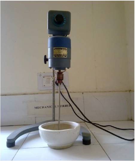
Figure 2. Mechanical Stirrer
Density of the coating slurry has been calculated conventionally. For this purpose a cube of size 5.025*5.14*0.91 cm3 has been prepared.
The viscosity of slurry is measured by Rheometer which is shown in Figure 3. The working operation of the Rheometer (DV-III Ultra) is to drive a spindle (which is immersed in the test fluid) through a calibrated spring. The viscous drag of the fluid against the spindle is measured by the spring deflection. Spring deflection is measured with a rotary transducer. The viscosity measurement range (in centipoises or cp) is determined by the rotating speed of the spindle, full scale torque of the calibrated spindle, the size and shape of the spindle and container in which the spindle rotates. The range of speed and temperature sensing are 0.01 to 250 rpm and -100 to 300°C respectively. The viscosity of coating slurry is measured at 28°C and 100 rpm for all twelve samples.
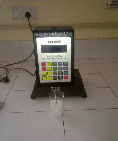
Figure 3. Rheometer
After the preparation of slurry, pattern is dipped into the primary slurry. The process is repeated two times, depending upon the thickness of coating. After being dry, secondary coating takes place on the pattern. Coarse powder formed mullite is also used as stucco material for support to secondary coat. The thickness of coating (primary and secondary) is found to be 3 to 4 mm for all samples. The coated patterns are shown in Figure 4.
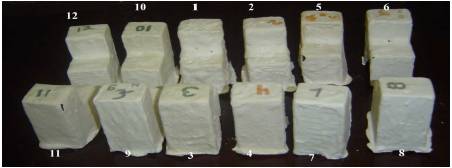
Figure 4. Coated Pattern (before Decomposition of Pattern)
Shell has been created by decomposition of expandable pattern with the application of heat. For this purpose Muffle furnace is used. As coated foam pattern is placed in the furnace, the foam starts to melt. At high temperature, foam starts to evaporate. After fully decomposition of foam, cavity creates. This process is called foam pattern removing. Here, muffle furnace is used to apply heat. Two methods have been used to remove the foam pattern-
Applying high temperature
According to this method, the coated patterns are kept in furnace at temperature 300°C for 30 minutes. Generated shell has defects such as expansion, bending, cracks, etc. The shell tends to expand and crack before complete decomposition of foam pattern which is shown in Figure 5 (a) & (b).
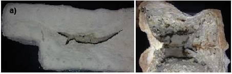
Figure 5. Applying, Direct High Temperature. a) Formation of crack on wall (External View). b) Bending and expansion of shell and uncompleted foam decomposition (Internal View).
Applying slow rise in temperature with preheating the shell
In this method, first, shell is preheated at 80°C for 30 minutes. After preheating, the temperature raises up to 120°C at a rate of 4°C/ minute. Shells are heated at constant temperature (120°C) for 20 minutes. Again the temperature rises up to 160°C at a rate of 4°C/ minute for 10 minutes and then heated at constant temperature for 20 minutes (as shown in graph). This process is repeated till foam does not evaporate completely. Figure 6 shows the graph between temperature and time. Shells have been created which are shown in Figure 7.
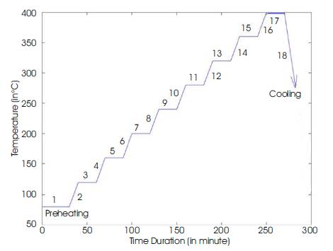
Figure 6. Foam Removal Process Graph (change in Temperature with respect to Time Per Stage)
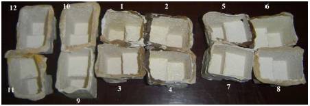
Figure 7. Applying Slow Rise in Temperature with Preheat (shells After Foam Pattern Removal)
This method is one of the simplest method in which all factors or criteria are allotted equal mark (ten marks) and the quality (property) of alternatives are assigned a number (obtained marks) out of maximum marks. Basically, this method is used to eliminate very bad alternatives for making easy and simple calculations. In this study, there are four very important factors (Bending/ Expansion Resistance, Distending Resistance, Internal Surface Finish and Crack Resistance). Twelve alternatives are used. Four good samples are selected by using this method.
The AHP is a mathematical tool which is used to determine the priorities of different decision alternatives via pair wise comparisons of decision elements with respect to common criteria. It provides an objective way for reaching an optimal decision for both individual and group decision makers [20]. This method is based on the problem decomposition into a hierarchy structure which consists of the elements such as: the goal, the criteria (sub-criteria) and the alternatives. The output of this method is a prioritized ranking, indicating the overall preference for each of the decision alternative. AHP has three major steps.
Table 1. The Saaty Rating Scale
Density of slurry of different composition has been calculated. The viscosity of slurry has been directly recorded for twelve samples from rheometer. These are shown in Table 2.
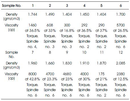
Table 2. Density and Viscosity of Twelve samples
The density and viscosity of slurry play an important role to achieve better dimensional accuracy and internal surface finish. The ratio of binder and refracatory coating powder is constant for all twelve samples. Here, sample no 7 and 12 have more density. Sample no. 6 and 7 have more viscosity. In all these samples (sample no. 6, 7 and 12), potassium silicate is used as binder. The reason is that potassium silicate binder is quickly absorbed by the powder formed coating material and produces more densed and viscused slurry.
Coated patterns are kept in a furnace at high temperature directly, then shrinkage rate will be fast and forms crack in shell. This problem can be minimized with the help of preheating and slow rise in temperature. The effects on shell, produced by foam removal process, have been investigated for each stage which are given in Table 3.
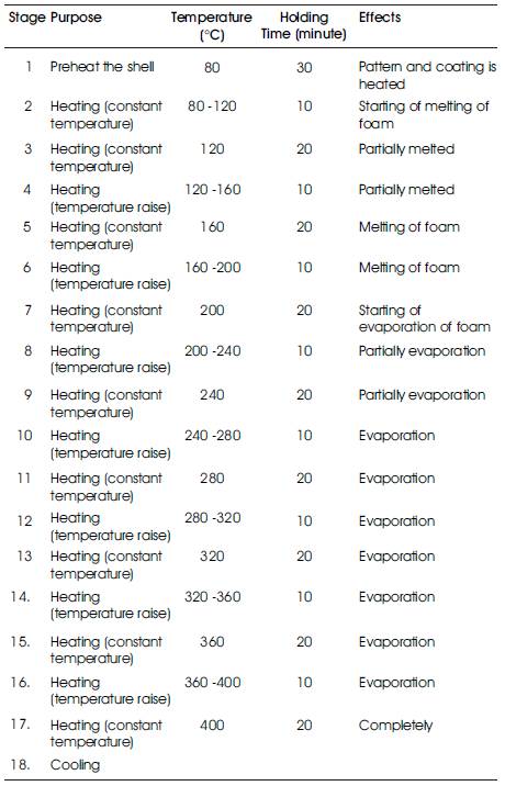
Table 3. Effects of Shell During Foam Removal Process
After foam removal process, each shell has been investigated and observed regarding to defects.
Sample No. 1
In this shell, cracks on corners and distending of shell are great problems. This is due to by vaporisation of binder which is mixed with coating material. Poor internal and external surface finish occurs. Crack on corner and distending of shell are shown in Figure 8 (a), (b) and (c).
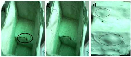
Figure 8. a) Crack, b) Distended portion on Internal Surface, c) Distended Portion on External Surface
Sample No. 2
In this shell, cracks on corners and distending of shell reduce. Surface finish of internal and external surface is poor. This is shown in Figure 9 (a), (b) and (c).
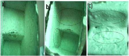
Figure 9. a) Crack b) Internal Surface Finish, c) External Surface Finish
Sample No. 3
In this shell, cracks on corners and distending of shell are lesser than samples 1 and 2. Internal and external surface finish is better than samples 1 and 2 which are shown in Figure 10 (a), (b) and (c).
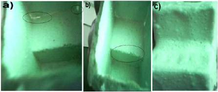
Figure 10. a) Internal Surface Finish and Break of Shell b) Crack c) External Surface Finish
Sample No. 4
In this shell, distending of shell and cracks on corners decreases with respect to sample 1, 2, and 3. This achieves better internal and external surface finish than sample 1 and 2, but lesser than sample 3. Very small expansion of shell takes place with compared to sample 1, 2 and 3 which are shown in Figure 11 (a) and (b).
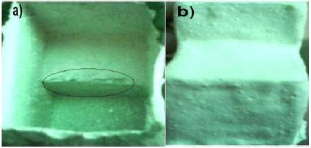
Figure 11. a) Crack and Internal Surface Finish, b) External Surface Finish
Sample No. 5
Expansion or bending of shell is a huge problem in this shell. Because dimensional accuracy depends upon the expansion of shell. Surface finish and dimensional accuracy are poor with respect to sample 1, 2, 3 and 4 which is shown in Figure 12 (a) and (b).
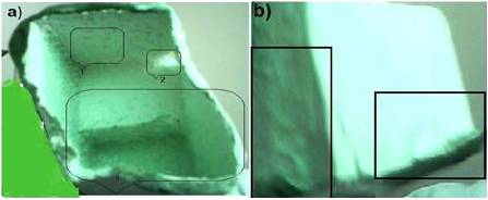
Figure 12. a) i) Internal Surface Finish, ii) Breaking of Shell, iii) Expansion of shell. B) Shell Bending (External View)
Sample No. 6
In this shell, there is no distending and expansion or bending of shell. Very small cracks are visible. Dimensional accuracy increases. Less strength of shell is observed as easy to break. Internal and external surface finish is better than sample 1, 2, 3, 4 and 5 as shown in Figure 13 (a) and (b).
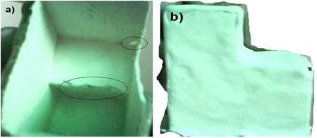
Figure 13. a) Crack b) External Surface Finish
Sample No. 7
Shell of sample 7 is shown in Figure 14 (a) and (b). Internal and external surface finish is better than all samples. Since, there is no distending and expansion or bending of shell so dimensional accuracy increases. The strength of shell is also better than sample 6, so break resistance property has improved.
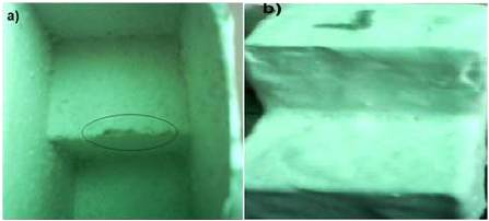
Figure 14. a) Crack on Internal Surface, b) External Surface Finish
For Sample No. 8
In this shell, there is no distending and expansion or bending of shell. So, dimensional accuracy is good. Internal and external surface finish is better than sample 1, 2, 3, 4, 5 and 6 as shown in Figure 15 (a) and (b).
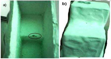
Figure 15. a) Crack on Internal Surface, b) External Surface Finish
Sample No. 9
Good dimensional accuracy has observed due to absence of distending and expansion or bending of shell. Internal surface finish is found better than sample 1, 2, 3, 4, 5 and 6, and less than sample 7 and 8 as shown in Figure 16 (a) and (b).
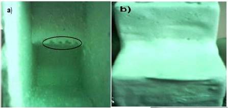
Figure 16. a) Crack on Internal Surface, b) External Surface Finish
Sample No. 10
In this shell, there is no distending, but bad dimensional accuracy has been achieved due to expansion or bending of shell. The expansion or bending of shell is found more than sample 1 to 9. Shell is shown in Figure 17 (a) and (b).
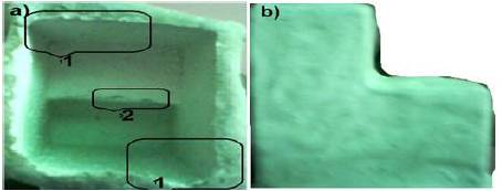
Figure 17. a) 1) Bending of Shell, 2) Crack on Internal Surface, b) External Surface Finish
Sample No. 11
The expansion or bending of this shell has found more than sample 1 to 10. So, dimensional accuracy is very bad. The cracks on corners are more. Internal surface finish is very poor. Shell is shown in Figure 18 (a) and (b).
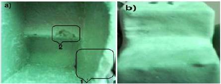
Figure 18. a) i) Bending of shell, ii) Crack on internal surface, b) External surface finish
Sample No. 12
The expansion or bending of this shell is more than sample 1 to 10 and equivalent to sample 11. So, very bad dimensional accuracy is observed. Shell is shown in Figure 19 (a) and (b).
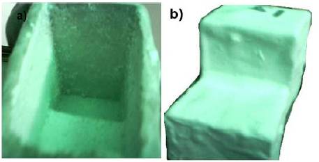
Figure 19. a) Internal surface Finish, b) External Surface Finish
Since, the main problems and defects (bending or expansion, distending, internal surface finish, cracks of shell)) are minimum in shell no. 7. So, shell no. 7 presents better results than other shells.
There are many criteria (properties of shell) on which the shell quality depends, as following.
In this investigation, the most important properties (bending or expansion resistance, distending or swelling resistance, internal surface finish, crack resistance of shell) are considered.
General Marking Method
As per the general marking method, the following Table 4 has been generated.
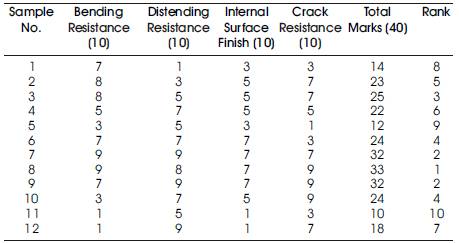
Table 4. Marks Assigned as per Properties of Shells
Here very bad samples (eight) are eliminated by using general marking method and rest four samples have been evaluated by AHP. So, four alternatives have been selected for further analysis.
Analytical Hierarchy Process (AHP)
According to General Marking Method, selected alternatives (sample no. 3, 7, 8 and 9) are used in AHP. For these alternatives and properties of shells, Saaty's Hierarchy Tree has been shown in Figure 20.
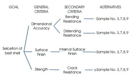
Figure 20. Saaty's Hierarchy Tree
Following steps are used for finding the best alternative as per AHP.
Select most important properties of shell (expansion or bending resistance as criteria A, distending resistance as criteria B, Internal surface finish as criteria C, and crack resistance as criteria D) and four good samples (S3, S7, S8 and S9).
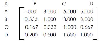
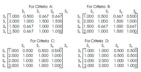
In this step, the pair wise comparision of individual criteria with respect to all criteria has been implimented. Similarly, the pair wise comparision of individual alternative with respect to all alternatives for each criteria, has been implimented.
For criteria A
For criteria B
For criteria C
For criteria D
In this step, the matrix form has been generated as per pairwise comparision.
For all criteria:
For all alternatives:
In this step, the eigen vectors are calculated by squaring the matrix and then adding each row as describe below .
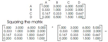
Again finding eigen vectors of the square matrix we get the following matrix (which is same to previous)

In this step, the best alternative is found by multiplying the criteria alternative matrix and criteria rank.
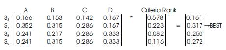
According to AHP Method, alternate sample no. 7 is selected as the best shell. This is because the important factor is considered as priority.