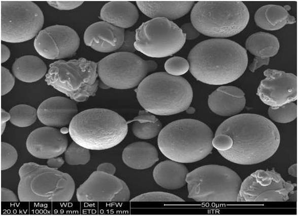
Figure 1. Typical Scanning Electron Microscope image Showing Morphology of Powder Particles
Processing of ceramics through microwave is well established route, but processing metallic materials through microwave has been a challenge. The present paper reports cladding of austenitic stainless steel with a Inconel 718 powder, developed through microwave hybrid heating route. The average thickness of clads was found to be nearly 1 mm. The microstructural study revealed excellent metallurgical bonding between clad and substrate. The clad layer is developed due to partial melting of outer layer of substrate and partial diffusion of powder particles into the substrate. The phases developed in clads were characterised using X-ray diffraction. Clads were further investigated using Field emission- Scanning Electron Microscope and Elemental Analysis. The clads developed were free from porosity and interfacial cracking.
Stainless steel is one of the most widely used engineering materials in various engineering applications because of the fact that it has good corrosion resistance in challenging environment. However stainless steel suffers failure mostly due to stress corrosion cracking. In applications like impellers of pumps and hydraulic turbines where blades have to bear corrosion as well as wear resistance, failure takes place due to Stress Corrosion Cracking (SCC). Hence it is necessary to combat such problem either by replacing the bulk material with other material having better properties or to increase the erosive wear resistance of steel by modifying the functional surface. The first method of replacing the whole bulk body with a improved material is not a economically feasible option. Instead improving the functional surface properties of the bulk material is a more pragmatic solution. The functional surface can be modified by various techniques like cladding/coating, carburising, nitriding etc [1]. Cladding is one such technique which involves overlay of suitable material-clad material on substrate, partial melting of substrate along with complete melting of clad material.
The popular surface modification techniques include Gas Tungsten Arc Welding (GTAW), Gas Metal Arc Welding (GMAW), Chemical Vapour Deposition (CVD), Physical Vapour Deposition (PVD), Ion Nitriding, Plasma Spraying, High Velocity Oxy Fuel Flame (HVOF), Laser Cladding. The CVD otherwise is an excellent process to develop overlays, but overlays on a large surface area or developing thick overlays make it a very costly technique. Laser cladding, on the other hand is one of the very popular cladding techniques. Attributes like excellent dilution control, low heat affected zone, faster cooling rate that helps to develop fine microstructure, that exhibits excellent wear characteristics etc are some reasons that make laser cladding a very popular technique. But limitations associated with laser cladding like high cost to process large areas, high thermal stress, and high distortion etc, inhibit its application in some areas [2].
Hence, an alternative and pragmatic solution that offers improved microstructures with reduced cost and faster processing time could be microwave processing. In the recent years microwave energy is being widely used to process a wide variety of engineering materials due to its specific characteristics like uniform heating, volumetric heating, rapid heating, penetrating radiation, selective heating of materials and controllable field distribution. Microwave energy heats the materials at molecular level that leads to volumetric heating, which results in finer microstructures. The volumetric heating also reduces the possibility of reduced thermal distortion.
Microwave material interaction depends upon the dielectric property of the materials. Dielectric property is the property that enables the material to get polarized in an oscillating electromagnetic field. Thus, depending upon the polarisability, a material may absorb or reflect microwaves. Microwaves are mostly used in processing of ceramics, ceramic composites, because they are good absorbers of microwave [3]-[6]. However, processing of metallic materials with microwaves is a challenging issue. Bulk metals tend to reflect the microwaves at room temperature. Later, it has been found that microwave heating can be applied to powdered metals, alloys and intermetallics both efficiently and effectively. Microwave processing of metallic material in the form of sintering was first reported by Roy et al. in the year 1999 [7]. Later many authors reported microwave sintering of metallic materials [8]- [12]. However, processing by bulk metallic material was reported by Srinath et al. [13] for microwave joining of material. Microwave cladding of metallic powder on metallic substrate was first reported by Sharma and Gupta [8-14] in the form of a patent. The authors also reported the development and characterization of nickel based EWAC powder using MHH [15].
Earlier only ceramics were processed with microwaves, because of the fact that they can easily couple with microwaves at room temperature within allowable frequencies. But processing metallic materials with microwaves is a challenging issue, because of the fact that bulk metallic materials reflect microwaves at room temperature owing to low skin depth [16]. In the light of above, the present paper aims to present the development and microstructural characterisation of Inconel 718 cladding on stainless steel substrate.
Procedures adopted in carrying out the cladding trails and other characterizations are described in the following sections.
Stainless Steel is well known for its excellent corrosion resistance, but it has poor erosion resistance. Properties like excellent wear and corrosion resistance at high temperatures coupled with high impact strength at cryogenic temperatures make Inconel 718 a perfect material to be used in conditions like turbine blades, jet engines etc [17]. Accordingly, these two materials were selected for present investigation.
For developing cladding of Inconel 718 on austenite stainless steel, Inconel 718 powder having a average particle size of 30 μm was used in this experiment. Figure 1 shows the SEM image of Inconel 718 powder, which shows the spherical morphology of the Inconel 718 powder. The chemical composition of Inconel 718 powder and substrate were measured using an Electron Probe Micro Analyser (EPMA) having an average beam diameter of 1 μm at an accelerating potential of 15 kV. Table 1 shows the chemical composition of Inconel 718 powder and SS-304 substrate. Figure 2 shows the XRD pattern of Inconel 718 powder, in which the peaks are dominated by Ni, Fe, and Cr, which are the major constituents of Inconel 718 powder.
Figure 1. Typical Scanning Electron Microscope image Showing Morphology of Powder Particles
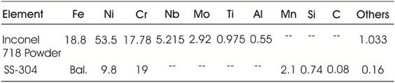
Table 1. Elemental Composition (wt %) of the Inconel 718 Powder and SS- 304
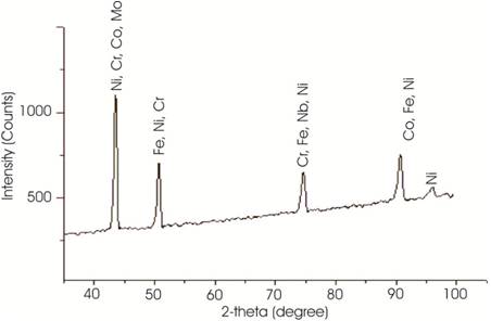
Figure 2. X-ray Diffraction Pattern of Inconel 718 Powder
Preparation of substrate and raw powder is very critical for successful development of cladding. In this experiment, the substrate used for cladding was thoroughly cleaned with acetone in an ultrasonic cleaner and finely hot dried prior to cladding. The substrate used was machined to the size 35x25x6 mm. In order to remove moisture from the powder, it was preheated in a vacuum furnace at 120°C for 4 hours.
The powder was preplaced manually on the substrate with a uniform thickness of 1 mm. Cladding was accomplished using a domestic multimode applicator (Make: LG Solar Dom) at a power of 900 W and frequency of 2.45 GHz. The whole arrangement was kept in refractory insulating box as shown in Figure 3. The refractory insulating box consists of material having low dielectric loss. Thus microwave can pass through easily without any interaction with it and it also act as a thermal insulator as it contains the heat in the hot zone. Thus it does not allow heat to lose from the hot zone. Since the bulk metallic materials tend to reflect the microwaves at room temperature because of lower skin depth [15]. Hence Microwave Hybrid Heating (MHH) was used for successful development of cladding of Inconel 718 powder on SS-304 substrate. The skin depth for Ni based powder is on the order in ~ 0.12 µm [15], but the skin depth is significantly less than the average particles size, i.e. 40 µm. However, the value of skin depth increases with increase in temperature [16]. Hence MHH technique is used in which charcoal powder is used as a suspector to raise the temperature of the powder particles through conventional modes of heat transfer. The susceptor couples with microwaves at room temperature, and its temperature rises and subsequently it transfers heat to powder particle through conventional modes of heat transfer through the separator [18]. By taking heat from the suspector, the temperature of powder particles increases up to the critical temperature so that above critical temperature the powder particles directly interact with microwaves and this causes melting of powder particles. Melting of the substrate, on the other hand is confined to thin layer only due to low skin depth of bulk metallic materials. A thin plate of 99% pure alumina (Al2O3) of thickness 1 mm was used as separator to avoid any contamination of powder particle with the suspector. Various parameters used in this experiment are given in Table 2. The partial melting of substrate in terms of surface layer and complete melting of powder particles was achieved using MHH technique. In MHH both conventional heating and microwave heating lead to uniform heating of the target material. This uniformity in temperature during MHH is also explained by Oghbaei et al. [11].
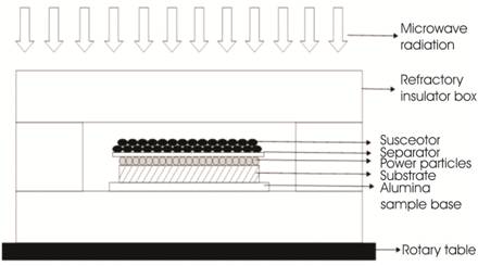
Figure 3. Schematic of Experimental Setup Used for Microwave Cladding
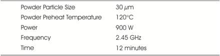
Table 2. Parameters used in Microwave Cladding
Prior to characterisation of the clad samples, the samples were cut using a diamond cutter (Make- Chennai Metco, Model- Baincut LSS) and were polished with 1 μm diamond paste to attain a mirror finish. After sectioning the samples they were washed in an acetone bath to remove any form of impurity. The various phases formed in the cladded sample were characterised using XRD pattern obtained at room temperature in a Bruker AXS diffractometer with Cu Kα X-ray. The scan rate used was 0.5°min-1 and scan range was from 20° to 100°. The analysis of the clad microstructure and elemental analysis were carried out using field emission scanning electron microscope at an accelerated voltage of 20 kV equipped with energy dispersive X –ray detector (Make: FEI, Model: Quanta 200 FEG) and electron probe micro analyzer (Make: JEOL, Model: JXA 8600M) respectively.
The microwave cladding of Inconel 718 powder was successfully carried out on stainless steel using Microwave Hybrid Heating (MHH). The chracterisation results of the developed clad are discussed in the following sections.
A typical XRD spectra of the developed clad (Figure 4) shows the presence of Ni3Ti, Ni3Al, FeNi, Cr3C7, and NiCr2O4 corresponding to 2-theta values of 39.223°, 43.234°, 51.026°, 74.892°, and 90.439° respectively. The Ni3Ti (2θ: 43.234°) and Ni3Al (2θ: 39.223°) are the main strengthening intermetallic compounds used in the Inconel 718 powder. The Ni3(Al, Ti) is a coherent precipitate with ordered FCC LI2 crystal structure [19]. The Ni3(Al, Ti) precipitate is an A3B type compound in which A is composed of electronegative element (Ni, Co, Fe) and B of electro positive elements (Al, Ti, Nb). The lattice parameter of the A3B compound roughly matches with that of main matrix. Hence it is possible to get coherency between the matrix and the precipitate. The advantage of coherency is that one can reduce coarsening of grain at higher temperature. The presence of FeNi (2θ:51.026o) and Cr3C7 (2θ: 74.892°) is due to dilution of the Fe and C from the substrate to the developed clad during microwave irradiation. The diluted C reacts with Cr, which is present in Inconel 718 powder and form chromium carbide (Cr3C7) during microwave irradiation. The formation of chromium carbide is due to the high affinity of chromium towards carbon. The presence of NiCr2O4 is attributed to the cause that cladding was carried out in atmospheric conditions, which resulted in formation of the nickel chromium oxide. The formation of NiCr2O4 was also reported in earlier work [17].
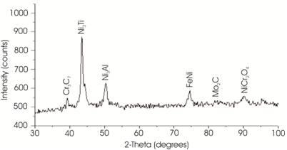
Figure 4. X-ray Diffraction Pattern of Inconel 718 Cladding
Figure 5 (a) shows the crystal structure of FCC of Ni matrix and Figure 5 (b) shows the crystal structure of ordered precipitate of Ni3(Al, Ti) in which Ni atom is located at centres of the atom and Al, Ti is located at corners of the cell. Advantage of adding both Al and Ti is that one can control the lattice parameter by changing the relative concentration of Al and Ti, because both Al and Ti are soluble to each other. By controlling lattice parameters, we can make these two match rather nicely. Lattice parameters of precipitate roughly match with the matrix, hence we get coherency strains. As we know deformation in a material is caused by slip motion of dislocations. Bergers vector gives the direction and magnitude of slip and it is important characteristic of the dislocations. Bergers vector is the shortest lattice vector as we go from one lattice point to another point such that there is no change in crystal structure. In FCC structure, the plane (111) is the closed packed plane and [1 1 0] is the closed packed direction. Thus, for dislocation to takes place, the a/2 <1 1 0> is the bergers vector for slip to takes place in Ni based matrix as shown in Figure 5 (a). But for ordered type of FCC structure the bergers vector is no longer a/2 <1 0 0>, it is actually a <1 1 0>, because in this case change in crystal structure takes place for going from one point to another, thus Bergers vector has double size than that of main matrix. Thus mechanism of strengthening is different here and it is as follows. For slip to take place in the precipitate without disrupting the crystal structure then in this case Bergers vector has double size than that of main matrix.
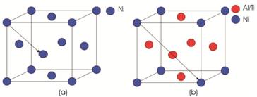
Figure 5. (a) FCC Structure of Ni Based Matrix (b) FCC Structure of Ordered Precipitate
A typical back scattered electron (BSE) image of the developed clad is shown in Figure 6 (a). The Figure 6 (a) shows the perfect bonding between the powder particles and the substrate. In Figure 6 (b), the back scattered electron image shows a typical dentritic structure developed. The developed clad are free from interfacial cracking attributed to volumetric heating associated with microwave heating process. The developed clad shows the planar growth of grains to an approximate distance of 100 to 150 µm from the clad/substrate interface after which the developed clad exhibits cellular structure. The condition that should be fulfilled for planer structure is given in equation (1).

Where, G is the temperature gradient, R is the growth rate, ΔT is freezing range, DL is the diffusion coefficient. Near the S/L interface the temperature gradient is high accompanied by a low growth rate that results in formation of planer structure. As the distance from S/L interface increases the temperature gradient decreases, coupled with increased growth rate which results in breakdown of planer structure. The mechanism of formation of columnar dentritic structure in the remaining clad structure is described as follows. During MHH, the powder particles absorb microwaves and gets heated up to higher temperature due to higher skin depth of the order of 0.12 μm at 2.45 GHz [15] . On melting the powder particles will start agglomerating and hence a pool of molten layer will form on the metallic substrate. Melting of substrate is however limited to a very skin depth only [15] . Thus substrate interface reaches the molten stage that facilitates the mutual diffusion of elements from the substrate to the molten powder layer and from the molten powder layer to the substrate with formation of metallurgical bonds. When the experiment is done, the molten powder layer will start solidifying on the substrate. Heat transfer will take place from the molten powder layer to the substrate due to limited thermal conductivity of the metallic substrate. The degree of undercooling in a solidifying melt is inversely proportional to the ratio of thermal gradient to growth rate (G/R) [20]. The thermal gradient in melted powder layer are steeper near to solid/liquid interface due to high thermal conductivity of the metallic substrate. Thus heat flow will takes place from the powder layer to the metallic substrate. The steep thermal gradient prevailing at the interface favours columnar dentritic growth in a direction opposite to the heat extraction. Thus, as shown in Figure 6 (a), columnar dendritic growth will be observed in the developed clad. Figure 6 (c) shows formation of Laves phase, MC carbide and cell boundary in a typical structure of the microwave developed clad. The Laves phases has a morphology generally ranging from isolated particles to continuous sheets and massive dentritic walls. Laves phases are composed of close packing considerations where nominal formula is of AB2, where A represents larger atoms Nb, Mo & Ti and while B represents Ni, Fe, & Cr [21].
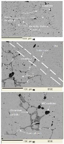
Figure 6. Microstructure of Inconel-718 Cladding (a) BSE Image Showing Typical Cellular Structure in the Clad Developed by MHH (b) Typical Substrate Clad Interface (c) BSE Image Showing Precipitation of Carbides at Cell Boundaries and Laves Phases
Solidification of Inconel 718 starts with primary liquid to γ reaction and proceeds causing enrichment of interdentritic liquid in Nb, Mo, Ti, C until an eutectic type reaction liquid to γ and Laves phases terminating the solidification process [20],[ 21] . In Nickel based superalloys, the major intermetallic phases are Laves phases (2H-, MgZn2 type) [22]. As the clad solidifies the recrystallised, dentritic network within the grains is formed from discontinuous, cross-linked sheets of lamellar MC carbides as shown in Figure 6 (c) [21].
The elemental analysis of the developed clad was carried out through EPMA. Typical results are presented in Figure 7. Figure 7(a) shows the points where the elemental analysis were carried out, while the corresponding elemental compositions are illustrated in the Figure 7(b) and 7(c). It is observed from Figure 7(b) that points 1 and 2 indicate presence of Fe as major alloying element. The grey phases are dominated by the chromium carbides as can be clearly seen; the percentage of Fe decreases as we approach towards the point 6. After point 6 the percentage of Fe is again increasing as shown in the Figure 7(b). The black phases are dominated by C. The concentration of Ni is more or less the same, except on point 6 where the concentration of Cr increase. Point 6 is taken in the centre of the grey region which indicated the higher concentration of Cr. The major alloying elements viz, Cr, Ni, Fe tend to be uniformly distributed in the clad region Figure 7(c) shows how minor alloying elements, Mo, Nb, Co vary in the clad. The various carbides of chromium are formed in the attributed to the high affinity of Cr towards C. Point 5 indicates increase in presence of Mo. Mo also tends to form carbides that provide wear resistance. Mo is also a carbide forming element formation of Mo2C. These carbides provide exceptional wear resistance to the clad, in which the significant contributions are from Cr and Mo carbides. Nearly uniform distribution of Ni/Cr is found in the clad. The effect of microsegragation around the dendritic cell formed is significantly owing to the fact that partial coefficient (K) is less than unity (K<1) from the phase diagram of Ni-Cr alloys.
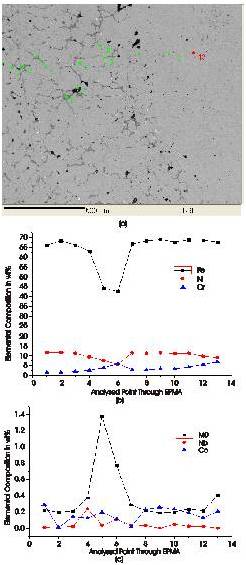
Figure 7. (a) Location for Elemental Analysis (b) Distribution of Major Alloying Elements in clad (c) Distribution of Minor Elements in Clad
The paper reports the feasibility of application of microwaves in developing the Inconel 718 cladding on Stainless steel substrate. Major conclusions drawn from the work are as follows,