Figure1. Turbine Electricity Generator
Green or renewable energies are energies that can be produced without many negative impacts to the environment and the earth can naturally recover these energy resources when using these sustainable energies. Currently many researches are focusing on design and development of sustainable energy technologies due to the shortage of global traditional energy resources. The wind power turbine systems are used to convert nature wind power to the electricity. This green and clean energy can be used in many energy applications. There are two types of wind power turbine systems including vertical axis and horizontal axis wind turbines. In this research, a new type of vertical axis wind turbine system with improved power converting efficiency is designed and developed through fundamental study, computer-aided modeling, aerodynamic analysis, computational simulation, and prototype testing.
The extensive researches in developing sustainable energy have been conducted in recent years to replace traditional energies due to the environment protection and shortage of traditional energies [1]. Green energy is one of the renewable energy resources that benefit the environmental protection. The energy products, such as electricity, can be produced from solar, wind, geothermal, and biomass [2]. Wind power system is one of the renewable energy resources used to generate the electrical power. Vertical-axis wind turbine is a wind turbine system in which the main rotor shaft is set up vertically [3]. Compared with the horizontal axis wind turbine, the vertical axis wind turbine has major advantages including lower level of electrical generator and transmitted gear box for fast and easy maintenance, large wind speed functional range from 2.5 m/s to 25 m/s, flexible facing angles between system and wind direction, lighter, reduced costs, lower noise, and easy to be installed [4]. There are two types of wind turbine systems: wind-resistant and wind-lifting types of wind turbine. In first type of wind turbine, the blade rotating speed is slower than the wind speed so that its power and efficiency is relatively low. In second type of wind turbine, the blade rotating speed is faster than the wind speed so that the power and efficiency is high and this type of wind turbine is being widely used [5], [6]. This paper focuses on the computer-aided modeling/simulation and prototype testing on new turbine blade design in wind-lifting type of wind turbine.
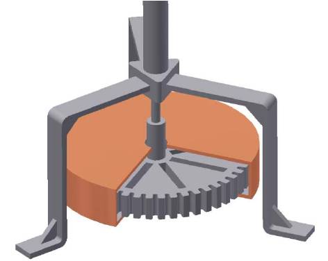
All the functioning components and mechanism in this new wind turbine system are designed through computer aided design (CAD) and 3-D modeling. Figure 1 displays the turbine generator at the bottom of this wind turbine system.
Figure 2 shows the balde design in this new wind turbine system.
Figure1. Turbine Electricity Generator
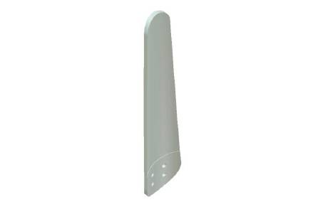
Figure 2. Blade Design in new Wind Turbine System
The fiber glass with high strength and low density is used for blade material. The blade geometrical design and lifting force can be determined through computer aided modeling, simulation and Finite Element Analysis (FEA) methodologies. This new turbine blade design can reduce frictional loss, ease manufacturing process, and lower production cost.
Blade element theory can be used to verify the performance of turbines and analyze the forces of an entire blade by dividing a blade body into many small segments to determine forces on blade elements. The total force on entire rotor can be determined through integration of all blade elements. The lifting force reaches the maximum when blade moves opposite direction to the wind direction and the minimum when blade moves same direction as wind direction. The critical parameters in turbine design include attacking angle α between oncoming air and blade moving direction, lifting forces acted at 1/4 chord from leading edge, pitching moment related to the aerodynamic forces, tangential and normal forces on turbine blade. The lifting and dragging forces are very important parameters in dealing with aerodynamic function of turbine blade including aerodynamic stall and flow boundary conditions.
Lifting force NL on each blade can be determined by equation (1):
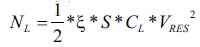
Here,
ξ -air density, CL- lifting coefficient, S- blade surface area, VRES- Resultant speed
Total wind power of turbine system can be calculated by equation (2):
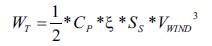
Here, WT– total wind power absorbed by a wind turbine, CP - power coefficient, ξ - air density, SS – turbine swept area, VWIND - wind speed
The Finite Element Analysis (FEA) is used to model and simulate the structure and stress in this turbine blade system. This turbine blade system can be divided into many small elements and the results from all elements can be calculated through computer-aided simulation to manipulate complex design parameters with high accuracy results.
Based on the above mathematical models, the computer-aided molding and simulation can be performed to determine if this new turbine blade system is properly designed. The diagram of cyclic force on turbine blade is shown in Figure 3. Figure 4 displays the equivalent stress and Figure 5 shows the total deformation in new turbine blade.
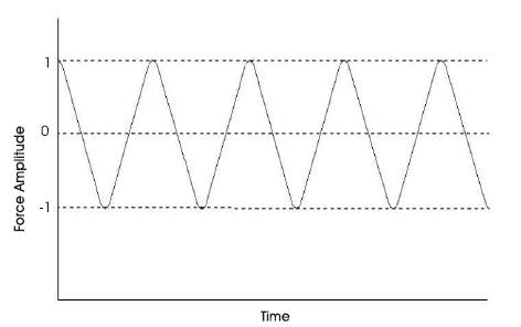
Figure 3. Diagram of Cyclic Force on Turbine Blade
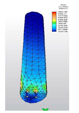
Figure 4. Equivalent Stress in the Turbine Blade
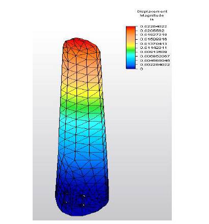
Figure 5. Total Deformation in the Turbine Blade
The above computational simulation results indicate that the maximum stress of 9089.76 psi produced in the turbine blade is less than material allowable strength of 25000 psi and total blade deformation of 0.0228 inch is within the material spec. Based on the computer aided modeling and simulation, this wind turbine system works properly.
The prototyped new turbine blade has been tested to determine the maximum equivalent stress and maximum deformation of the blade. These testing results can be used to verify the structural analysis from computer-aided modeling and simulation. It can also provide information for future design improvement. The preliminary prototype testing results are shown in Table 1.
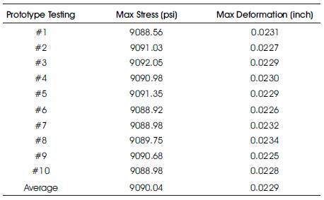
Table 1. Prototype Testing on New Turbine Blade
The preliminary prototype testing shows that the average maximum stress in turbine blade is 9090.04 psi and average total blade deformation is 0.0229 inch. The prototype testing results are very close to the results from computer-aided simulation.
The future work on this research will focus on the following items, based on current analysis through computer-aided modeling and prototype testing
The wind power is one of the green or sustainable energies which are considered to be environmentally friendly sources of power and energy with no pollution. Wind power can be converted to the useful energies including using wind turbines to make electricity. Wind power is an unlimited, free and clean power energy resource that can be applied in many different areas. This research paper introduces a new wind turbine blade system design based on computer-aided modeling, mathematical analysis, computational simulation, and prototype testing. Both computational simulation and prototype testing show close results which validate the credibility and feasibility of this new wind turbine blade system design.