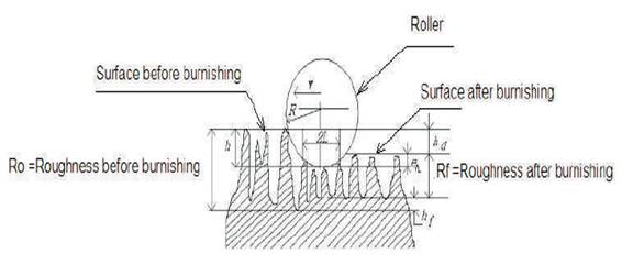
Figure 1. Burnishing Process
The present experimental work was conducted on a lathe machine to establish the effects of various roller burnishing parameters by burnishing force, burnishing feed and burnishing speed on the surface roughness and surface hardness of EN-31 steel. A simple designed roller-burnishing tool was used throughout the experimental work presented in this paper. It was observed that all the parameters studied the effect of surface finish and surface hardness to varying degrees. The surface roughness Ra first decreases and then increases with increasing burnishing force. The effects of burnishing feed and burnishing speed on the surface finish also showed similar trends. Results showed that the burnishing feed, burnishing speed and burnishing force has also significant effect on surface hardness.
Burnishing, a plastic deformation process can be used to finish the surfaces. Burnishing is a cold-working process in which plastic deformation occurs by applying a pressure through a very hard and smooth ball or roller on a metallic surface. Improvements in surface finish, surface hardness, wear resistance, fatigue resistance, yield and tensile strength and corrosion resistance can be achieved by the application of this process.
In today's production of machines and instrument components, finishing processes are becoming more and more important. Increasing attention is being paid to the quality of the surface finish obtained. Surface finish is important not only as an appearance of expert workmanship; it also has a positive and prolonged effect on the functioning of machine parts. It affects the resistance to wear, load-carrying capacity, tool life, corrosion and fatigue. Poor surface finish may neutralize the effect of tolerances and require more power to operate the mechanism. Surface finishing processes like grinding, polishing, lapping and honing are commonly employed to improve the surface finish. However, in recent years, attention has been paid to operations, which improve the surface characteristics, by plastic deformation. Such operations are sometimes referred to as plastic surface deformation. Roller burnishing falls into this category and is becoming more widely employed. Burnishing is a cold-forming process, in which the metal near a machined surface is displaced from protrusion to fill the depressions. Figure 1 shows burnishing process in which a roller of radius R is moving with velocity V. Ro is the surface roughens before burnishing. After burnishing the surface roughness is Rf. A literature survey shows that work on the burnishing process has been conducted by many researchers (Murthy et al, 1981; EI-Axir et al 2000; Luo et al, 2001;) and their study revealed that the different parameters like force, feed, speed effect the surface finish and hardness to a very high extent. Hasan et al in 1996 worked on commercial aluminum and brass and studied the influence speed, feed, force, number of passes and ball diameter on surface roughness and hardness. Hasan et al in 1997 showed that ball burnishing force give lower surface roughness and grater surface hardness than roller burnishing. Hasan et al in 1997 and 2000 worked on Al-Cu alloys and found that the different parameters like force, feed, speed, initial surface roughness, initial hardness, ball diameter and use of different lubricant effect the surface finish and hardness. Luo et al in 2001 worked on aluminum and found that even surface roughness of work-piece is lower than initial surface roughness of burnishing tool. Shiou et al in 2003 determine the optimal parameters by applying the Taguchi's L18 matrix method for ball burnishing. EI-Axir et al 2003 worked on aluminum alloy, brass and three steel and studied that burnishing speed and depth of penetration, effects the surface hardness and out-of-roundness. Luca et. al in 2005 showed that besides producing a good surface finish, the burnishing process has additional advantages over other machining processes, such as increased hardness, corrosion resistance, and fatigue life as a result of the producing compressive residual stress. A.A. Ibrahim et al compared experimental work and fuzzy model and showed that good surface characteristics can be achieved by using center rest ball burnishing tool. Burnishing force, burnishing feed and number of balls in single pass are the most important parameters that play an important role in controlling the values of all surface characteristics.
From Literature it seems that no burnishing work has been done on EN 31. As EN 31 has a lot of application in rubbing surfaces due to its properties of high hardness after treatment such as bearings. So the present paper examines the use of a new roller-burnishing tool to give good surface characteristics, such as higher surface finish and surface hardness on EN-31. The effects of three burnishing parameters (burnishing speed, burnishing feed and burnishing force) on two different responses (surface roughness and surface hardness,) are comprehensively studied.
Figure 1. Burnishing Process
In this work, EN-31 was used as a work piece material. The chemical compositions are displayed as in Table 1.
The raw material was received as cylindrical bar of EN-31 from market and got tested for Composition. The diameter of bar was 28mm. The bar was cut into pieces each having a approximate length of 300mm. The work piece was turned to a diameter of 25mm and the work piece was divided into 12 equal parts of 25mm each. The surface roughness and surface hardness of work piece was measured before burnishing and after burnishing at each region. Average values of three measurements have been recorded for each region.
In this work, tests were performed with external moving roller-burnishing tool. All of the burnishing tests were performed under lubricated conditions. Only three burnishing parameters were chosen, namely burnishing speed, burnishing feed and burnishing force. Other parameters, such as number of pass, roller diameter and lubrication were held constant throughout the work. Since dry burnishing conditions produced poor surface finish, it was decided to apply lubricant during all tests. Also, a constant roller diameter of 32 mm was used throughout this investigation. The burnishing conditions are summarized as in Table 2.
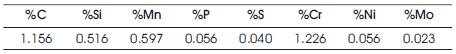
Table 1. Chemical composition
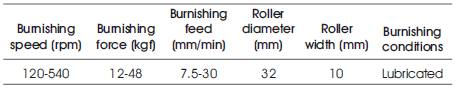
Table 2. Summary of burnishing conditions range
The Roller burnishing tool was designed and fabricated for the present experimental study. The various parts of roller burnishing tool are shown in Figure 2. High carbon high chromium steel bearing of inside & outside diameter 10/32mm and having Rockwell hardness of 80 HRC has been taken as roller. The bearing can be removed easily from the tool for changing by removing the pin. The bearing holder was supported by a pre-calibrated spring, which could apply the required force when it was pressed on work piece surface. The use of spring was important to reduce stitching due to friction between roller and work piece. When bearing was pressed against the surface of work piece, the spring supporting the bearing would be compressed with relation to the applied burnishing force. By measuring the compression of spring, the burnishing force can be calculated.
The experiments were conducted on lathe machine for turning and Roller burnishing of the specimens. Roller burnishing tool was fitted on the tool past mounted on the carriage assembly in the same way as any other cutting tool. The burnishing was done by changing different input parameters (burnishing speed, burnishing feed and burnishing force). The surface roughness of specimen before and after burnishing was recorded with the help of Surface Roughness tester-(model SJ-201 make mitutoy). The surface hardness of specimen before and after burnishing was recorded with the help of Rockwell Hardness testing machines. Block diagram for experimental set up is shown in Figure 3. Analysis of the out put parameters (surface roughness and Surface Hardness) w.r.t to the input parameters was done with the help of graphs.
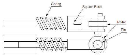
Figure 2. Two views Roller Burnishing Tool
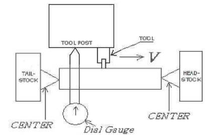
Figure 3. Block Diagram For Experimental Set Up
Minitab 15 software was used for design of experiment. For design of experiment, Taguchi L-16 method was applied. Total 48 runs of experiments were suggested by L-16 method.
Figures 4 to 10 shows the variation surface roughness Verses burnishing force at different burnishing feed and burnishing speed. The graphs shows that as burnishing force increases the surface roughness decreases, but after a definite value of burnishing force the surface roughness starts increasing with increases in burnishing force. This happened because at high burnishing force the cutting of metal takes place. This point of force is the critical point beyond which the surface roughness starts increasing. From Figures 4 to 7 it is clear that at high value of burnishing force the critical point of force beyond which the surface roughness starts increasing, shifts towards right, which shows that at high burnishing feed, we can apply high burnishing force. As in Figure 4, the value of critical burnishing force is 24 kgf at a burnishing feed of 7.5 mm/min and the value of critical burnishing force is 36kgf at a burnishing feed of 30 mm/min. Similar trends are there in Figures 5 to 10. From Figure 7 and 10 we got the minimum value of surface roughness 1.8 µm at burnishing force of 48 kgf, burnishing feed 30 mm/min and burnishing speed 540 rpm.
From Figures 8 to10 we can see that the lines at low burnishing speed are above the lines at high burnishing speed, which shows that at high burnishing speed good surface finish is obtained as compare to low burnishing speed. From Figures 8 to 10 it is clear that at low burnishing speed and high burnishing force, we got a very high value of surface roughness. The reason for this may be that at low burnishing speed the tool got sufficient time to remove the metal. Figures 8 to 10 shows that up to critical value of burnishing force the lines at different burnishing speed are converging towards each other, which shows that the effect of burnishing speed goes on decreasing towards the critical value of burnishing force. After critical value of burnishing force the lines at different burnishing speed are diverging from each other, which shows that the effect of burnishing speed goes on increasing beyond the critical value of burnishing force. From Figure 4 the minimum value of surface roughness with constant burnishing speed 120 rpm is 0.86 µm at burnishing force 36 kgf and burnishing feed 30 mm/min. Figure 5 shows minimum value of surface roughness with constant burnishing speed 200 rpm is 0.39 µm at burnishing force 48 kgf and burnishing feed 30 mm/min. In Figure 6 minimum value of surface roughness with constant burnishing speed 340 rpm is 0.38 µm at burnishing force 48 kgf and burnishing feed 30 mm/min. Figure 7 indicate minimum value of surface roughness with constant burnishing speed 540 rpm is 0.18 µm at burnishing force 48 kgf and burnishing feed 30 mm/min.
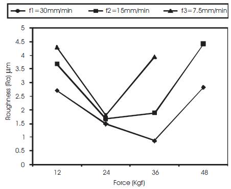
Figure 4. Burnishing force Vs surface finish at constant burnishing speed 120 rpm
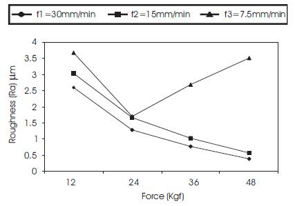
Figure 5. Burnishing force Vs surface finish at constant burnishing speed 200 rpm
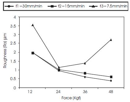
Figure 6. Burnishing force Vs surface finish at constant burnishing speed 340 rpm
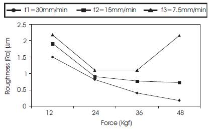
Figure 7. Burnishing force Vs surface finish at constant burnishing speed 540 rpm
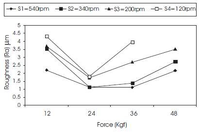
Figure 8. Burnishing force Vs surface finish at constant burnishing feed 7.5 mm/min
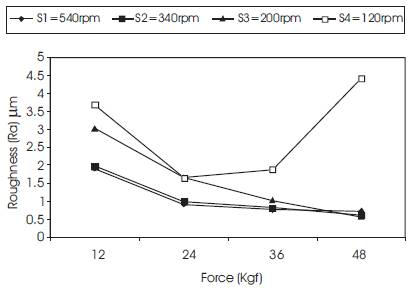
Figure 9. Burnishing force Vs surface finish at constant burnishing feed 15 mm/min
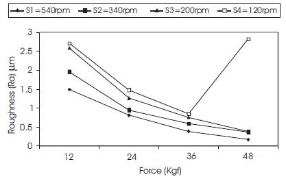
Figure 10. Burnishing force Vs surface finish at constant burnishing feed 30 mm/min
From Figures 4 to 7 we can see that the lines at low burnishing feed are above the lines at burnishing feed, which shows that at high burnishing feed good surface finish is obtained as compare to low burnishing feed. We can see from Figures 4 to 7 that up to critical value of burnishing force the lines at different burnishing feed are converging towards each other, which shows that the effect of burnishing feed goes on decreasing towards the critical value of burnishing force. After critical value of burnishing force the lines at different burnishing feed are diverging from each other, which shows that the effect of burnishing feed goes on decreasing towards the critical value of burnishing force. From Figure 8 the minimum value of surface roughness with constant burnishing feed 7.5 mm/min is 1.1 µm at burnishing force 24 kgf and burnishing speed 540 rpm. Figure 9 shows the minimum value of surface roughness with constant burnishing feed 15 mm/min is 0.57 µm at burnishing force 48 kgf and burnishing speed 200 rpm. From Figure 10 the minimum value of surface roughness with constant burnishing feed 30 mm/min is 0.18 µm at burnishing force 48 kgf and burnishing speed 540 rpm.
From Figure 11 to 13 it is very clear that as the burnishing force increases the surface hardness increases. The reason for this may be that the surface material got closely packed as we increase the burnishing force. The increase in surface hardness with increase in burnishing force is almost linear. In Figure 13 the maximum value of surface hardness is 21 HRC at burnishing force 48 kgf. Also from Figure 11 to 13 the lines at low burnishing speed are above the lines at high burnishing speed, which shows that we got hard surfaces at low burnishing speed that is with increase in burnishing speed the surface hardness decreases. The reason for this may be that at low burnishing speed the material got the time to closely packed. By comparing the Figure 11, 12 and 13 it is observed that at low burnishing feed the surface hardness obtained is less as compared to high burnishing feed, which shows that with increase in burnishing feed the surface hardness increases. The maximum value of surface hardness is 21 HRC at burnishing feed 30 mm/min.
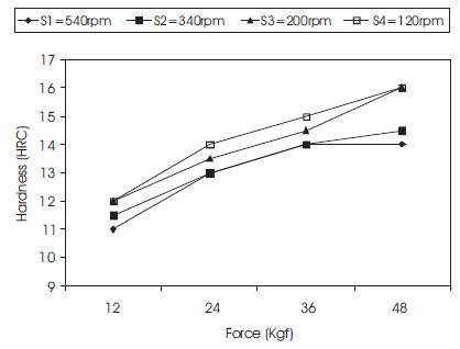
Figure 11. Burnishing force Vs surface hardness at constant Feed 30 mm/min
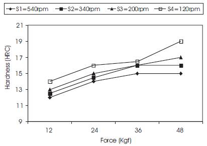
Figure 12. Burnishing force Vs surface hardness at constant Feed 15 mm/min
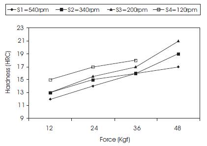
Figure 13. Burnishing force Vs surface hardness at constant Feed 7.5 mm/min
As we increases burnishing force, surface finish obtained increases. The surface finish become maximum at particular value of burnishing force and with further increase in burnishing force, cutting of metal started and surface finish decreases. Minimum surface roughness (Ra) obtained is 0.18 μm. As we increases burnishing speed, surface finish obtained increases. The surface finish become maximum at particular value of burnishing speed and with further increase in burnishing speed, cutting of metal started and surface finish decreases. As burnishing feed increases surface roughness decreases. The minimum value of surface roughness was recorded at force 48 Kgf, speed 540 rpm and feed 30 mm/min.
As we increases burnishing force, surface hardness increases. Maximum surface hardness obtained is 21 HRC. With increase in burnishing speed, surface hardness decreases. Similarly with increase in burnishing feed the surface hardness decreases. Maximum hardness value of was recorded at force 48 Kgf, speed 200 rpm and feed 7.5 mm/min.