Figure 1. Block Diagram for V3F Drive
Decision to install and commission a modern lift or an elevator in institutional, commercial, or residential building has been considered to be a challenging task. The project assignment does not only involve a multidisciplinary expertise, but also requires permissions and approvals from various government and private authorities like Municipal Corporation, Public Works Department (PWD), Architect, Structural Engineer, etc. Despite the vast, wide spread of the intricacies of the topic, this article intends to provide the readers with some general and a few detailed important factors while making decisions towards lift installations. Numerous options of elevators are available in the market with different qualities and costs, which make the selection process a difficult task. Selecting a lift signifies to be a Multi-criteria Decision Making (MCDM) problem and it is illustrated that the decision can be effectively addressed by Analytical Hierarchy Process (AHP). The article intends to present some useful tips that can be adopted while installing the elevators to the technical decision makers.
Vertical transport systems, also called as Lifts or Elevators, are essential for easy and comfortable movement of people or goods from floor to floor in tall and high rise buildings. The necessity of handling of material or movement of object, typically at challenging highrise sites and difficult terrains had initiated developments of elevators. Steel beam constructions are extensively used in the passenger and freight elevators today. The installation of lift involves huge cost of mechanical components, electrical machines and cables, civil structures, etc. Lifts were invented as simple rope or chain hoist systems.
Higher capacity elevators usually operates automatically through touch controls, whereas a lift operates on pressure selected through button. Worldwide, an elevator is mostly a synonym for lift. Lifts are designed to transport only one person, while elevators are designed to transport more than a person or goods. Simply, elevators lift humans or objects to desired vertical distance. It is a room like structure but elevator is sometimes used for under construction buildings, etc. Simple elevator elevates materials, machines, people, etc. Elevators are also sometimes a electrical staircase, which moves up itself.
Elevators were developed for the movement of raw materials on hillsides. The material handling technology based on construction of rails, ropes, steel beam, etc., is then eventually evolved for the movement of the passenger. Steam power operated elevators were extensively employed in mines and factories.
During the next stage of development, hydraulic systems with oil pressure, pressure to raise and lower the elevator car became popular in residential and office premises (Celik and Korbahti, 2006). However, one of the disadvantages of hydraulic elevators was need of a pit below the lift shaft for piston movement. Moreover, for higher travels of a cabin car would require larger piston and larger stroke, resulting in bulky powerpack. Therefore, researchers and designers had to focus on a viable option for multistoreyed buildings with improved safety, compactness, and robustness. Hence, despite the hydraulic systems being popular for about half a millennium, problems related to oil leakages, cable damages leading plummeting of cars to bottom, bulkiness of hydraulic power packs, oil coolers, counter wirghts, damage to structure of building, etc., laid a foundation for altogether a new generation of electrical elevators.
A cabinet enslosure carrying live stock load or passengers that are manuevered up and down over a vertical guide rails in a shaft or hoist way by mechanical means are referred as lifts. Since its inception 100 years back, the technology has witnessed mechanical, hydraulic, and electrically operated elevators with gradually increasing robustness, reliability, comfort and safety. Earlier, lift drive mechanisms were powered by steam and water hydraulic pistons or by hand. Modern elevators are a beautiful conglomeration of multidisciplinary engineering fields involving civil, mechanical, electrical and electronics systems.
Steel ropes moving over grooved pulleys provide necessary friction-traction required for motion of cabin car against the counterweight. Synchronizing two lifts simultaneously moving in opposite directions can act as complimentary counterweights to each other and therefore are considered to be much more economical. Use of hydraulic lifts are commonly found in limited to low to mid-rise buildings. Ropes and hydraulic power provide engineering suitability to raise and lower the lift cars. Installation of lengthy hydraulic cylinders for a multistoreyd high rise building becomes tedious and sometimes impractical. The latest amongst the elevator technologies essentially incorporates smooth gearless microprocessor controlled magnetic drive motors, directly installed over the lift car itself. The complete assembly moves with the car and therefore does not require a separate machine room. Space requirement is one of the influential factors in new lift installations in high rise buildings. Every building comes with its own varied requirements like age of the building, number of floors, dimensions of the well, and usage patterns. Therefore, required customization can sometimes affect the economics of lift installation contract.
While making the decision to install a lift, the first and foremost important part to be considered is building regulation, which includes authentic floor wise architectural drawing containing elevation, building plan showing lift shaft, and also approved by competent authority like Municipal Corporation, Certificate from Structural engineering consultant.
The second part focuses on technical specifications, which includes Capacity, Speed (mps), STOPS, Drive Power Supply, Operation, Rescue, Machine Traction Media, Car Finish, Car door and landing door frame, Hand Rails, Ventilation, Flooring, Car fittings, Fire Rating Doors, Hoist way Dimensions, Door Operator, Care Operating Panel, Car Position Indicator, Power, Brakes, Emergency Services, Emergency Car Light Unit, Door Screen, Door Time Protection, Emergency Alarm Bell, Extra Door Time of Lobby and Parking, Door Open/Close Button, Maintenance Service/Guarantee Warranty, Civil Work inside Shaft, etc.
The third part is about finance and accounts like taxes, freight, packaging, transport, delivery period, commissioning, and annual maintenance contract.
The fourth and the last part is to release Purchase-cum-Work Order and part payments if necessary as per P.O. whereupon the manufacturer submits the General Arrangement Drawing (GAD). GAD shows the proposed arrangement of the lift equipment in the lift well, pit and entrance areas, including the overall sizes and weights of all major items of lift equipment. It also indicates the magnitude, position and direction of all loads imposed on the building structure by the lift and its associated equipment on the general arrangement drawings. The verified and approved GAD by the customer then needs to be resubmitted to the manufacturer for forwarding to the material estimates and the licensing authority such as PWD Inspector. Material procurement and the actual installation, erection and commissioning are followed by inspection, testing and licensing by the PWD Lift Inspector.
The lift manufacturer and supplier is responsible for ensuring the selected equipment meeting the functional requirements as indicated within the documentation, and including for all the features included in this specification.
The equipment specified for the installation should include the following factors:
In addition to the traffic analysis, available lift shaft size is the main criterion that decides the capacity of lift in terms of weight to be hoisted. This is specifically indicated in terms of the number of persons that can be accommodated in the lift car. Modern lifts are typically suitable for a shaft size 1.8 m x 1.9 m or bigger than that and can carry 10 persons weighing 680 kg. This lift is shaft size and capacity are bare minimum, wherein a modern elevator with best suitable configuration can be fitted. Rated load and size of the car should be practicable, the same as the existing lift cars; where the car size can be increased, this should be considered.
The major strength parameters in the modern lifts that make them up to date are Machine Room Less (MRL), gearless, central opening and sliding auto-door, coated flat belts as traction media, Microprocessor based Variable Voltage and Variable Frequency (VVVF) with AC motor drives for Jerk free ride, Protection Against Power Fluctuations (PAPF), Manual as well as Automatic Rescue Device (ARD), travel speed range from 1.02 mps to 1.78 mps, auto dialer, Intercom system for car cabin, Closed Circuit Television (CCTV) camera, car top and lift pit and most of the parts made in good quality stainless steel. Some of the modern lift units are also equipped with regeneration type, which sends back the unused power or the power that is generated during travel, back to the main grid. This technology is expected to replace the older versions soon. The other featured accessories of decorative, aesthetics and elegance look including vandal proof car operating panel, mirror, ceiling, flooring, Light-Emitting Diodes (LEDs), ventilation and air conditioning, etc., further adds value to vertical travel experience.
There could also be specific requirements of elevators based on needs of application or field like vertical transport of grains, food (dumb elevators), radio antennas, bridge towers, open cast or closed underground mines, dams, and power plants, where only Special Purpose Elevators (SPE) can be implemented.
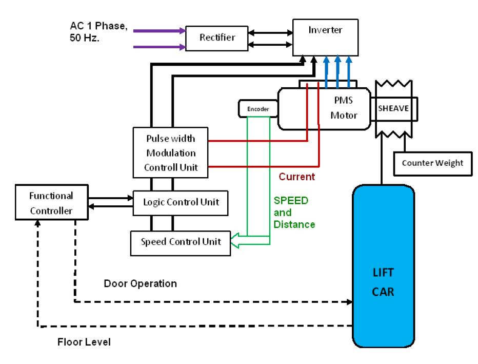
MRL elevators are a type of traction elevators. They do not require a machine room on the top of the hoist way (Tetlow, 2007). Therefore about 120 Sq. ft. space is saved. MRL consists of a magnet, permanently fixed to a synchronous motor which functions with V3F drive, thereby reducing otherwise required considerable space for conventional motor. Figure 1 shows the block diagram for V3F drive. The traction hoisting machine is placed on the top side wall or the bottom of hoist way. Hence the main controller (230 V AC) is placed on the top or bottom floor (bottom drive elevators – popular in japan) next to the landing doors behind the locked cabin with or without keys for ease of maintenance, repairs and emergency purposes. Aesthetically, pleasing and without key are preferred. Some MRL elevators have controller cabinet installed within the door frame to save space, however they are very rare. Electrical equipments are protected from direct contact with shrouded terminals. A direct acoustic communication system between the control panel and the lift car is usually provided in the modern MRL lifts. MRL elevators are normally incorporated into new building design with lowrise (4-4 floors) to mid-rise (20 floors).
Figure 1. Block Diagram for V3F Drive
Modern MRL incorporates gearless, Permanent Magnet Synchronous (PMS) motors replacing conventional induction motors. The design of modern gearless MRL elevators eliminates machine room requirement and therefore saves substantial building space. Gearless MRL technology can be used for both front and, front and rear open elevator cars. The assembly of gearless machines comprises a drive motor, drive sheave, bedplate, brake rotor, supporting bearings, and a deflector or double wrap sheave. The assemblies are super silent in their operation and insulated from the building fabric to ensure no noise or vibration pollution affecting the people nearby.
Gearless MRL eliminates the necessity of gearbox thereby saving a lot of space and weight. Gearless PMS AC motor is the most power efficient, particularly when installed with the regeneration inverter unit. The gearless drive system uses 40% less energy than the traditional geared lift. This means savings of a few thousand kWh/year for a single lift. The PMS gearless MRL drive technology powered by a 3VF inverter unit directly connected to sheave, controls the necessary torque throughout the full speed range of the elevator.
There are instances during operation of elevator wherein a small amount of power is generated by the elevator system itself, e.g. during lowering of the cabin car or applying electrical brakes or retarding stages before coming to rest at very landing. The smart microcontroller diverts this power to storage device, this cirucuitary arrangement called regen unit receives excess power and may either utilize for elevator or send to power grid. Loaded elevators descend faster due to gravity. In this case, instead of consuming the power, motor delivers rather generating the power, which in turn could be used for other domestic applications. On the other hand, in conventional drive systems the heat generated during operation calls for dissipation by means of air conditioning system. The PMS with regeneration facilitates bidirectional energy flow.
Harvesting regenerative power is an effective approach for gearless MRL to enhance their efficiency. It is the emerging technology used on electric or hybrid transport systems to recoup some of the energy lost during stopping. Regenerative energy has to be injected in conventional power source. In gearless V3F MRL design for vertical transport systems, when the elevator speed is reduced, directional stability is controlled through governor and a microprocessor based control system. The regenerated energy is saved in a storage battery and used later to power the motor. Regenerative system takes energy wasted during operation or in braking, and turns it into usable energy (Balaji et al., 2011). It improves energy efficiency of the lift. The electricity generated during operation or braking varies according to the speed of the lift. So to utilize the generated electricity completely, a suitable Electronic Control Unit is necessary.
Drive systems in most of the modern elevators offer the regeneration option. Regeneration unit (regen) is an excellent option; firstly in extensively travelling busy elevators and secondly, for that, it utilizes the power produced by the lift itself by conserving energy. This would be one of the most favored features specifically when the world eyes for efficient and effective systems in energy harvesting and optimum utilization. The regen unit contributes significantly for saving the electrical power during running of a lift. However, a power requirement for gearless MRLs in standby mode is little higher compared to power requirements of hydraulic elevator drives or electrical. Gearless MRLs otherwise when operational consumes much lesser power and proves to be more beneficial and economical. To eliminate these demerits, researchers and design engineers are working to develop hybrid systems incorporating partial power supply from solar systems as well.
Additionally, space, building material and hence construction time required in installing MRL is less since it requires no separate machine room. Also, space for headroom and pit is saved considerably. By locating all the lift equipment in the shaft, it offers architects and designers the freedom to design without a machine room, hence freeing up valuable space inside the building for more productive use. Moreover, the compact gearless machine, a larger car for carrying more number of passengers (or weight) can be fitted into a standard shaft space.
The motor has two separate electric brakes equipped with a mechanical hand release and monitoring switches. A tacho-generator is also built into the machine assembly. The brakes of modern MRL are able to stop the lift at 125% of designing load. Travelling Contractors, brake resistances, EMC filters, and motor reactors are integrated into the compactly designed inverter.
Modern MRL also consists of flexible, high strength belts which saves much space and allow to incorporate the minimum size of hoisting sheave. These belts are about 30% lighter than the conventional steel ropes. The ratio of size of sheave to size of belt rope, in modern MRL is about 16:1, which is very less when compared to that of conventional traction elevators. The smaller ratio allows the smaller drive sheave and therefore this does not only save the space, but also it is energy efficient to operate (Sachs, 2005). Use of LED for lift car and the lift well as, leads to about 5 to 10% energy savings. Incorporating various methods simultaneously can yield an energy saving of 30–35% within elevator classes (Sachs, 2005).
Rope developed with a carbon fiber core and a high - friction coating are extremely light and this reduces energy consumption in high rise buildings (Asvestopoulos et al., 2010). Further it mimimizes the weight of its moving components, such as the hoisting ropes, compensating ropes, counterweight, elevator car, and passenger load (Akhavan et al., 2006; Al-Adaileh and Al-Atawi, 2011; Al- Alawi et al., 2007, Chew et al., 2008).
Moreover, carbon fiber resonates at a completely different frequency to steel and most other building materials. The elevator downtime caused by building sway is reduced. The weight bearing capacity of carbon polymer reinforced fibre rope is better and the life of these ropes are also twice as that of steel ropes (Barney, 1991; Bashiri and Badri, 2011; Beckman, 1999).
Modern gearless MRL lifts are provided with a load weighing device to detect an overload condition within the car. The overload detecting strain gauge switch or pressure switch is incorporated in the system. The gauge is fitted to the car crown bar/rope anchor arrangement. This switch overrides the car movement control and signal an alarm buzzer and electronic message on the car indicator until such time as the overload is reduced.
In view of the expectations of value for money from the customers, the multinational elevator companies are focusing to develop high speed and maximum travel span MRLs. The gearless MRL machine unit and governor are located in the overhead of the hoistway. The Gearless MRL elevator is becoming the more popular choice amongst mainstream elevator companies (Cheng, 2011; Chennamaneni, 2006).
It is accepted that the maintenance of gearless MRL is expensive, but it is rarely time consuming, provided the support and services are prompt, when compared with conventional elevators. Even though, inclusion of new control, operation and safety features has increased the complexities of MRLs, they are becoming more reliable and safe. Troubleshooting complexity is also significantly increased since it is often difficult for the service technician to get all the components required to solve the problems. Additional labour cost makes the MRLs to be most expensive to maintain.
Economy, System Performance, safety and comfort are the most important factor that needs to be complied for stringent and regular inspection guidelines based on elevator maintenance laws. Most of the defects can be prevented by considering three major maintainability criteria, i.e. design and specification, construction or installation, and inspection and maintenance (Chew et al., 2008).
The standard MRL represents a green technology since it does not use oil and therefore no possibility of spill overs to the environment. Further, most of the gearless MRL components are manufactured off-shore, therefore shipping is also greener.
The year 2004 may well be remembered in the elevator industry as a watershed year. For low-rise applications, these machine-room-less elevators are coming down in cost. This technology is going to rapidly wipe out hydraulics from the market.
Based on a brief review of elevator installations in past 3 years, it is observed from the data of Form-A (permission to eret lift), Form-B (Lift erection completion report) and licenses issued by Public Works Department (PWD) Electrical Engineering Division that gearless MRLs are being installed extensively and traditional geared traction elevators have become almost obsolete.
Until recently, low-rise elevators (up to five or six stories) were typically hydraulic, and mid-rise elevators (up to 20 or 30 stories) were geared, traction machines. Hydraulic elevators pump hydraulic fluid, moving a piston that pushes the elevator cab up and lowers it back down (Davenport and Prusak, 1997; Zander and Kogut, 1995).
Selection and evaluation of lift suppliers is also as important as selection of specification of elevators in modern competitive environment to increase effectiveness and utility due to an extensive variety of manufacturers. It has become more and more complicated to meet the challenges of international competitiveness, and as the decision makers need to assess a wide range of alternative suppliers based on a set of conflicting criteria. Because of these reasons, supplier selection has got considerable attention by the academicians and researchers (Jha et al., 2013).
Minimizing cost of installation without sacrificing the safety, reliability, and ease of operation is one of the most desired goals for a selection of elevator. Apart from cost, there are many factors, such as technical specifications, quality, reliability of equipment, maintenance aspects, energy efficiency, running costs, etc., that needs to be considered for elevator selection. Considering the multiple criteria decision requirement, the elevator selection can be formulated as Multi Criteria Decision Making (MCDM) problem. There are numerous MCDM techniques, such as Analytical Hierarchy Process (AHP), Technique to Order Preference by Similarity to Ideal Solution (TOPSIS), Preference Ranking Organization Method for Enrichment Evaluation (PROMETHEE), ELECTRE, VIKOR, etc., popularly used in many equipment selection decisions (Temiz and Calis, 2017).
The analytical hierarchy process was developed by Saaty (1980), which is based on additive weighing process. AHP has been widely used in many MCDM problems and researchers have applied many versions of AHP combined with other approaches, such as Fuzzy, Genetic algorithm, etc. In application to the problem, AHP involves three major stages: first, to form a hierarchical structure of criteria and alternatives; second, make a pairwise comparison of the decision criteria/alternatives and third, to prioritize the alternatives based on relative ranking as shown in Figure 2.
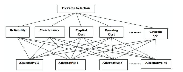
Figure 2. Structural Hierarchy
The stepwise procedure of AHP is presented as follows (Görener, 2012):
Step 1: Construct the structural hierarchy.
Step 2: Construct the pairwise comparison matrix.
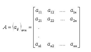
In this step, the pairwise comparison of the criteria is performed. The 'n' criteria problem will result in a square matrix (A) of size (n×n). In this matrix, the elements a (i, j= 1, ij 2, 3 ….., n) correspond to the weights of the criteria based on the preference. This is given in equation (1).
Step 3: Construct normalized decision matrix.
Step 4: Construct the weighted, normalized decision matrix.
Step 5: Calculate the Eigenvector and the maximum Eigenvalue.
Step 6: Calculate the consistency index and consistency ratio.
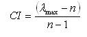
The relation between the entries of the matrix A is defined as the consistency and the Consistency Index (CI) can be calculated using equation (2). Here, l represents the max maximum Eigenvalue.
Based on the consistency index, the Consistency Ratio (CR) is calculated using equation (3). The CR decides whether the evaluations are sufficiently consistent with the chosen criteria weights and any further iterations or revisions are needed. The consistency ratio has to be smaller than 0.1, otherwise more iterations of evaluation has to be performed to improve the consistency.

The AHP methodology assists to determine the relative rankings of the alternatives consistent with the criteria and choose the best alternative based on the priority. AHP calculations can be done using electronic spreadsheets, software packages, etc.
Modern elevators are a beautiful conglomeration of multidisciplinar y engineering fields involving civil, mechanical, electrical and electronics systems. A feature based comparison of lift specifications shows that the latest elevator technologies incorporate smooth gearless microprocessor controlled magnetic drive motors directly installed over the lift car itself. Space requirement is one of the influential factors in new lift installations in high rise buildings. Technical specifications like General Arrangement Drawing (GAD), Capacity, Speed (mps), STOPS, Drive Power supply, Operation, Rescue, Machine Traction Media, Car Finish, Car door and landing door frame, Hand Rails, Ventilation, Flooring, Car fittings, Fire Rating Doors, Hoist way Dimensions, Door Operator, Care Operating Panel, Car Position Indicator, Power, Brakes, Emergency Services, Emergency Car Light Unit, Door screen, Door Time Protection, Emergency Alarm Bell, Extra Door Time of Lobby and Parking, Door Open/Close Button, Maintenance service/Guarantee Warranty, Civil work inside shaft etc. are the most significant decision factors in the installation of a modern elevator. A quick checklist including reliability, maintenance and energy efficiency would also be helpful. Rated load and size of the car should be practicable.
Modern MRL incorporates gearless, Permanent Magnet Synchronous (PMS) motors replacing conventional induction motors. The design of modern gearless MRL elevators eliminates machine room requirement and therefore saves substantial building space. Gearless MRL technology can be used for both front and front and rear open elevator cars. The gearless drive system uses 40% less energy than the traditional geared lift. The PMS gearless MRL drive technology powered by a 3VF inverter unit directly connected to sheave controls the necessary torque throughout the full speed range of the elevator.
Regeneration Drive systems (regen) in most of the modern elevators offers an excellent option in extensively travelling busy elevators for conserving energy. However, a power requirement for gearless MRLs in standby mode is little higher compared to power requirements of hydraulic or electrical elevator drives. Thus MRLs are energy efficient during operation and requires significantly less service time.
For mid to low-rise applications (5 to 25 storeyed buildings), gearless MRLs are becoming best options. Gearless MRLs cater perfectly not only to the needs of the architects, builders and users, but also to the environment by earning carbon credits and national economics by saving energy.
Numerous options of elevators are available in the market with different qualities and costs, which make the selection process a difficult task. For that reason, the MCDM methods, which take into account multiple criteria and rank the alternatives analytically can be used effectively to solve the selection problem.