(1)
Additive Manufacturing (AM) is emerging as an innovative technology distinguished from traditional manufacturing techniques because of its ability to produce complex, fully functioning and end-use products with great design flexibility. This technology is going to have utmost impact on future manufacturing industries. In the present research study, among the seven AM processes, laser based powder bed fusion (L- PBF) or selective laser sintering is gaining more importance due to its capability to process both metals and non-metals starting from metals to polymer and ceramics. Most L-PBF machines are imported and expensive. Hence R V College of Engineering and KCTU (Karnataka Council for Technological Upgradation) - Government of Karnataka have jointly developed an indigenous L-PBF machine, which has been utilized to conduct studies on effect of processing parameters on sintering of iron, silicon carbide, and polyethylene powders. Three key process parameters, laser power, hatch spacing, and scan speed were chosen for this study. The experiments have been conducted according to L9 orthogonal array based on Taguchi methodology of design of experiments adopted to determine the optimum sintering conditions for each of the three materials. Iron powder was optimally sintered with a laser power of 90 W, scan speed of 500 mm/s, hatch spacing of 0.1 mm, at spot size of 0.5 mm. Silicon Carbide powders were sintered with a laser power of 20 W, scan speed of 25 mm/s, hatch spacing of 0.4 mm, at spot size of 1 mm. Polyethylene powders were sintered using a laser power of 22.5 W, hatch spacing of 0.3 mm, Scan speed of 500 mm/s, at spot size of 1.5 mm. The influence of these parameters on energy density was 3 determined. In order to produce iron parts, an energy density of 18 J/mm was required, while in case of Silicon carbide 3 3 parts, it was 21 J/mm and for polyethylene, it was 1.5 J/mm .
Additive Manufacturing (AM) also known as rapid prototyping or 3D printing technology can be defined as “the process of joining materials to produce three dimensional products from 3D Computer-aided Design (CAD) models, in layer by layer sequence, converse to conventional subtractive manufacturing methodology” (Calignano et al., 2017). According to ASTM Standard F2792, AM processes are classified into seven categories; out of these seven, three categories operate with lasers (Pinkerton, 2016). AM consists of 8 steps in converting virtual CAD model into functional product (Gibson et al., 2010). Three most potential benefits of this technology over traditional manufacturing practice are improved resource efficiency, extended product life, and reconfigured value chains (Schmidt et al., 2017). Laser based powder bed fusion (L- PBF) and direct energy deposition are preferably used for processing of metals (Lee et al., 2017). During early stages of AM technology, CO and Nd:YAG (Neodymium- 2 doped Yttrium Aluminum Garnet; Nd:Y Al O ) were used.
However, as research continued, use of laser moved from Nd:YAG solid state lasers to present commercially used Ytterbium doped fibre lasers (Goodridge et al., 2011).
This laser sintering process makes use of high energy laser to sinter powder particles directly into 3D objects in a layer by layer sequence. Once a layer of powder is consolidated via sintering, which involves localised heating powder and simultaneous cooling of sintered layer, recoating blade or the roller spreads new layer of powder and laser scans this layer according to cross section of CAD model. This process continuous until whole product is produced (Wong and Hernandez, 2012). The consolidation process involves three binding mechanisms, namely solid state sintering, partial or liquid state melting, and full melting (Schmidt et al., 2017).
Metals, ceramics, and polymers are most commercially used materials in production sectors and have wide range of applications around the world. Zhou et al. (2015) have investigated the balling tendency in laser melting of tungsten and explained the effect of double scanning on density and concluded that double scanning resulted in 3 increment of density from 15,200 to 16,000 kg/m . Ghosh et al. (2014) have studied laser sintering of mixture of Aluminum, Titanium dioxide, and Boron carbide powders using Taguchi method to optimize the process parameters and concluded that a layer thickness of 200 microns, the laser power of 1000 W, scan speed of 6000 mm/min, and hatch spacing of 600 microns were the optimized parameters which resulted in desired micro-hardness of the laser sintered parts. Uhlmann et al. (2015) have investigated sintering of Tungsten Carbide Cobalt. Energy Density (ED) was calculated by equation (1).
where ED is energy density (J/mm ), PL is laser power (J/s), V s is scanning speed (mm/s), h is hatch spacing (mm), and l s z is layer thickness (mm) and concluded that higher energy 3 density of 1670 J/mm caused dynamic re-melting and evaporation. A lower value of energy density equal to 185 3 J/mm caused porosity.
Shahzad et al. (2014) have produced complex Zirconia (ZrO ) shapes with polypropylene with a concentration of 70% as the sacrificial binder by indirect selective laser sintering using a CO laser, with optimized parameters, 2 namely laser power 3 W, Scanning speed 1250 mm/s, and layer thickness 130 μm and hatch spacing 0.1mm. The density of the parts was increased from 32% to 54% by Pressure Infiltration (PI) at 16 MPa with a 30 volume % ZrO 2 suspension. Goodridge et al. (2010) have conducted experimental study on laser sintering polyethylene powder with average particle size of 120 microns and concluded that scan speed of 5000 mm/s, hatch spacing of 0.15 mm, a layer thickness of 0.1 mm and laser power of 18 Watts were desirable for sintering of polyethylene. Bai et al. (2016) have showed that there was effect of processing conditions, namely laser power, scan speed, powder bed temperature and double laser sintering, and effect of thermal history had effect on tensile properties of laser sintered polyethylene and concluded that double scanning of layers and slow cooling rate enhance improved tensile strength.
In this report, study on optimization of process parameters, namely Laser power (P ), Scan Speed (V ), and Hatch L s Spacing (H ) using Taguchi's design of experiment was s done on laser sintering of Iron, Silicon carbide and Polyethylene powders using CO laser and optimum levels 2 of these parameters for all three powders were determined.
The materials used in this study were iron (Fe) and Silicon Carbide (SiC) powder with average particle size 100 μm. Iron powders were procured from M/s Serena Inc, silicon carbide powders from Super Abrasives, Bangalore and polyethylene (PE) powders of average particle size 150 μm were procured from Oswal Hi-tech in Bangalore. The materials were characterized by Scanning Electron Microscopy (SEM), Fourier Transformation Infrared Spectroscopy (FTIR) for determining polymer chemical compounding and X ray Diffraction (XRD) for metals and ceramics as shown in Figure 1.
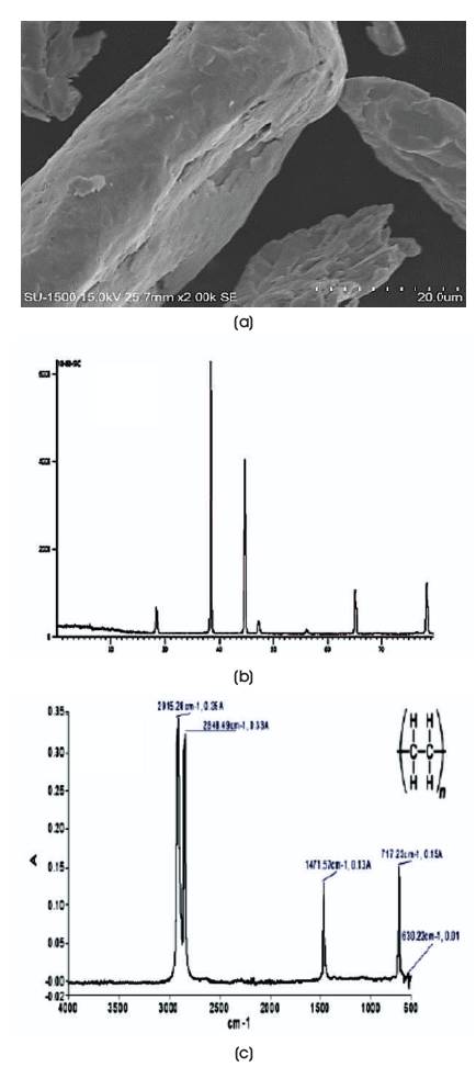
Figure 1. (a) SEM Image of Fe, (b) XRD Plot of SiC, (c) FTIR Spectrum of PE
Figure 1 (a) shows SEM image of iron powder. It is evident that the powder particles are not spherical, however it has been reported in literature that iron has acceptable level of laser absorption at 10.6 μm.
Figure 1 (b) shows XRD plot of silicon carbide powders. The powders are crystalline and hence an a- SiC phase. The color of pure SiC is white, however in the presence of iron in trace quantity, it will have a green color.
Figure 1 (c) shows the FTIR spectra for polyethylene. The -1 -1 peaks at 2915.36 cm and 2848.12 cm clearly indicate that C-H bands are present in polyethylene.
The powder bed fusion machine used in this study is an indigenously built sintering machine. Laser used in this machine is CO laser, which has a wavelength of 10.6 μm 2 and can generate power of 300 W operating in pulsed mode, having beam diameter of 80 micron. Manual mechanism is used for spreading of powder layer of thickness 100 μm. Sintering operation was carried out in controlled Argon atmosphere. The image of the L-PBF machine designed and developed at R V College of Engineering is shown in Figure 2.
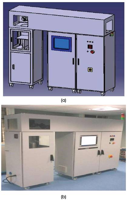
Figure 2. (a) CAD Model of Laser Based Powder Bed Fusion System, (b) Machine jointly developed by RVCE and KCTU, Government of Karnataka
Laser sintering process consists of various steps starting with CAD modelling. A square of size 20×20 mm was modelled using CATIA V5 software and uploaded to machine system. Powder of layer thickness approximately 100 μm was deposited. Figure 3 shows the steps involved in layer by layer manufacturing.
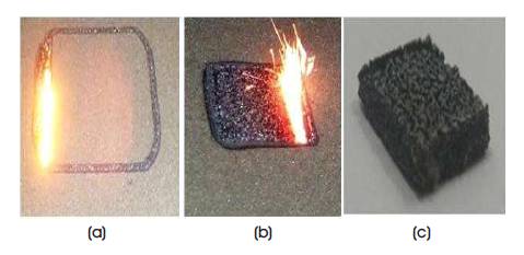
Figure 3. Images of the Laser Sintering of Iron Powders using L-PBF System
During sintering, many process parameters play an important role on Energy Density (ED) of sintered part (Bai et al., 2016). In this study, parameters such as laser power (P ), L scan speed (V ), and Hatch spacing (H ) were varied for s s sintering metal, ceramic and polymer powders. Layer thickness (L ) was kept constant at 100 μm. Taguchi's t method of design of experiments was used to conduct experiments. L9 orthogonal array was used to conduct experiments to optimize process parameters for all the three powders. Table 1(a) and (b) show the list of process parameters and corresponding levels for Fe powders and the L9 orthogonal array, respectively.
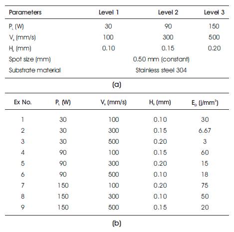
Table 1. (a) Experimental Conditions for Sintering Fe Powders using L-PBF Process, (b) L9- Orthogonal Array of Experimental Conditions for Sintering Fe Powders
Similar experimental plan was implemented for Silicon Carbide and Polyethylene powders. Table 2 (a) and (b) show the process parameters and their respective levels for PE and SiC powders, respectively.
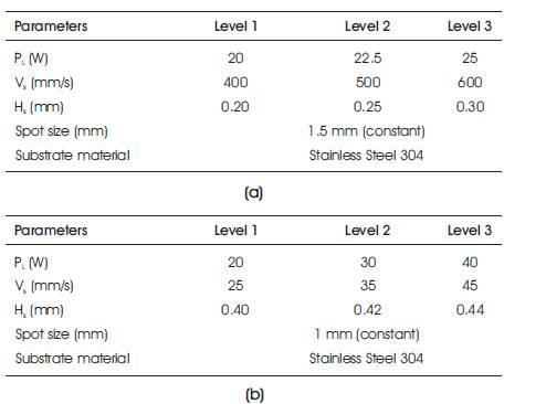
Table 2. (a) Experimental Conditions for Sintering Polyethylene Powders using L-PBF Process, (b) Experimental Conditions for Sintering SiC Powders using L-PBF Process
The experimental results of L9-orthogonal array were analyzed. The percentage effects of each parameter on energy density were plotted on pie chart as shown in Figure 4 (a). The pie chart clearly shows that hatch spacing had 28% influences, scan speed had 46% and power had 26% influences on energy density for sintering iron powders.
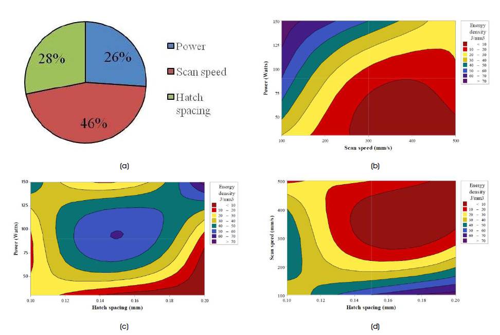
Figure 4. (a) Pie Chart showing the Influence of P , V , H on ED, (b)-(d) Counter plots of ED as a function of P , V and H L s S L S S
Figure 4 (b) shows that in the laser power range of 50 to 110 W and a scan speed of 150 to 500 mm/s, there is a good laser power absorption. Energy density that contours below 3 20 J/mm will result in sintering, while energy density greater 3 than 20 J/mm would lead to melting of powder particles which is undesirable.
Figure 4 (c) shows contour plot of laser power and hatch 3 spacing. Here, again in contour region of 20 J/mm , there is good sintering observed for iron powders.
Figure 4 (d) indicates that at lower energy density level of 3 <20 J/mm , there is incomplete sintering. While above 40 3 J/mm , the powder surface begins to accumulate heat leading to melting of powders. Hence, here again the 3 optimum energy density for sintering is ~ 20 J/mm . This is achieved with scan speed in the range of 200 to 480 mm/s and with hatch spacing of 0.1 to 0.2 mm.
The optimized parameters for sintering of iron powders were - laser power of 90 W, hatch spacing of 0.1 mm, scan speed of 500 mm/s and a spot size of 0.5 mm, and the 3 corresponding energy density was 18 J/mm . Table 3 shows the microstructure of iron powders sintered under optimized laser processing parameters.
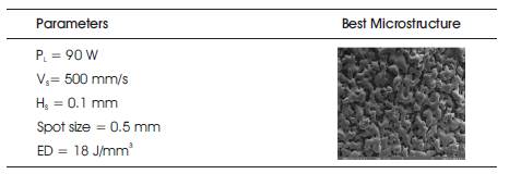
Table 3. Optimized Processing Conditions for Sintering Fe Powders using L-PBF Process with corresponding Microstructure of Sintered Iron
Silicon Carbide powders were sintered using L-PBF process as per L9 orthogonal array. The percentage influence of process parameters on energy density is as shown in pie chart in Figure 5 (a). It shows that hatch spacing had 28% influences, scan speed had 45% influences, and power had 27% influences.
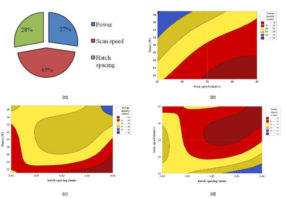
Figure 5. (a) Pie Chart showing the Influence of P , V and H on ED of Sintering of SiC Powder, (b)-(d) Counter plots of ED as a L S S function of P , V and H .
Figure 5 (b) shows in the laser power range of 20 to 32 W and with scan speed range of 26 to 30 mm/s, there is good absorption of laser power. Energy density in the range of 20 3 to 25 J/mm will result in sintering, while energy density less 3 than 20 J/mm would lead to partial sintering of powder particles, which results in a compound of weak and unsintered powder particles which is undesirable.
Figure 5 (c) shows contour plot of laser power and hatch spacing. Here, good sintering is observed in the region of 3 range 20 to 25 J/mm with hatch spacing of 0.4 mm.
Figure 5 (d) shows at scan speed of range 25 to 40 mm/s, hatch spacing of range 0.4 to 0.44 mm and optimum 3 energy density of 21 J/mm resulted good periods of laser power exposure for SiC powder particles to avoid balling effect.
The optimized parameters for sintering of SiC powders were - laser power of 21 W, hatch spacing of 0.4 mm, scan speed of 25 mm/s and a spot size of 1 mm, and the 3 corresponding energy density was 21 J/mm . Table 4 shows the microstructure of SiC powders sintered under optimized laser processing parameters.
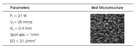
Table 4. Optimized Processing Conditions for Sintering SiC Powders using L-PBF Process with Corresponding Sintered Microstructure of Silicon Carbide
The percentage influence of process parameters on energy density of polyethylene is as shown in pie chart in Figure 6 (a), which clearly showed that hatch spacing had 60% influence and scan speed, laser power had 34% and 6% influences, respectively on energy density of sintering of polyethylene powders.
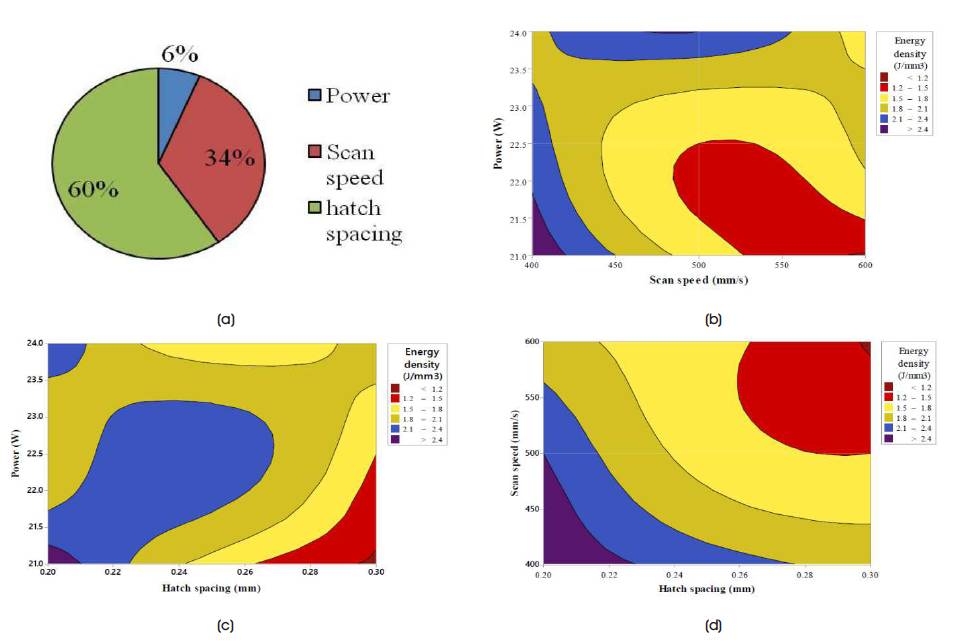
Figure 6. (a) Pie Chart showing the influence of P , V and H on ED of Sintering of PE powder, (b)-(d) Counter plots of ED L S S as a function of P , V and H
Figure 6 (b) shows that in the laser power of range 21 to 23 3 J/mm and a scan speed of 450 to 600 mm/s, there is good laser power absorption with energy density 1.2 to 1.8 3 J/mm . Scan speed below 400 mm/s and laser powder above 30 W results in melting of powder particles which is undesirable.
Figure 6 (c) shows contour plots of laser power and hatch 3 spacing. Here, again in the contour region of 1.5 J/mm with hatch spacing of range 0.25 to 0.30 mm, there is good sintering observed for polyethylene powder.
Figure 6 (d) shows that at higher energy density level >1.8 3 J/mm , there is melting of powder particles due to small hatch spacing. Hence, here again the optimum energy 3 density for sintering is ~1.5 J/mm , which is achieved with scan speed in the range of 400 to 500 mm/s and with a hatch spacing of 0.26 to 0.30 mm.
The optimized parameters for sintering of polyethylene powders were - laser power of 22.5 W, hatch spacing of 0.3 mm, scan speed of 500 mm/s and a spot size of 1.5 mm, 3 and the corresponding energy density was 1.5 J/mm . Table 5 shows the microstructure of SiC powders sintered under optimized laser processing parameters.
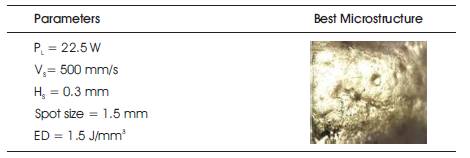
Table 5. Optimized Processing Conditions for Sintering Polyethylene Powders using L-PBF Process with corresponding Microstructure of Polyethylene
In this study, laser sintering of iron, silicon, and polyethylene powder were successfully performed using Laser assisted Powder Bed Fusion process. Taguchi's design of experiments technique was adopted to determine the influence of parameter on sintering of powders. Based on the results obtained, the following conclusions were drawn.
It is a great privilege to express our deep sense of gratitude to Department of Mechanical Engineering, R V College of Engineering, Bengaluru, India and KCTU Government of Karnataka, India for supporting to conduct sintering processes in R & D Department, RVCE Bengaluru, India.