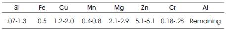
Table 1. Standard Chemical Composition as per ASM Norms
Friction Stir Welding (FSW) is an innovative and promising solid state joining process invented by The Welding Institute (TWI). FSW is considered to be one of the most significant developments in metal joining technology over the last two decades. Experiments were conducted on 6 mm thick AA7075 aluminum plates with copper coating on the faying surfaces. The plates were joined by friction stir welding under optimized conditions and the weldments were investigated for mechanical and metallurgical properties to identify the influence of the intermetallic compound (IMC) formed during the process. Results show substantial improvement in mechanical and metallurgical properties with copper coated weldments over conventional weldments. Crack initiation and specimen fracture were observed in the thermo mechanically affected zone of the weldments with superior tensile strength, finely elongated grains and reduced defects.
The Friction Stir Welding technique is a solid-state welding process, avoids the conventional defects associated with the fusion welding processes [1,2] . Absence of traditional fusion welding defects, reduced distortion and residual stresses, improved mechanical and metallurgical properties, fine grains with primary particle fragmentation, are the major benefits of FSW as welding takes place without melting of the plates [3]. This method overcomes the difficulties like hot cracking, porosity and distortion which happens oftenly in fusion welding. During welding, the material is frictionally heated to a temperature, at which it becomes more plastic. The heat of friction and the plastic flow arising from the rotating tool produces significant microstructural changes, which leads to a metallurgical bond with local variation in the mechanical properties of the weld. P. Cavaliere et.al have characterized the 2198 Al – Li weldments for mechanical and microstructural properties by numerical evaluation and experimental validation. Thermographic infrared techniques were applied for investigating the real-time crack initiation, growth and propagation behavior due to fatigue. The crack initiation, crack propagation and thermo elastic stress analytical analysis are validated with the experiment results. Decrease in ductility and an increase in necking in the weldments were reported with microstructures and the thermal profiles [4,5]. Yingchun chen et.al have performed experiments to analyze the failure locations in the heat affected zone on the retreating side through weld morphology, onion ring visibility for different set of weld conditions [6]. T.Tanaka et.al have investigated the weld joint strength of mild steel and AA7075 aluminium alloys by analyzing the intermetallic compound at the weld interface EPMA and FESEM analysis were performed for quantitative verification of the thickness of the hard brittle IMC [7]. Weifeng Xu et.al have examined the microstructures, second phase particles, mechanical behavior and the fracture surface to investigate the effect of degree of deformation to grain growth. Observations made on the weldments indicates that the crack initiation is found always on the retreating side of the welded joint in bend test [8]. A.Kosttka et.al have examined the one micron layer IMC of aluminium and magnesium using TEM to find the crystallographic information Al/Mg IMC reaction and phases that leads to the formation of nano size grained particles which is a part of the solid state welding of dissimilar materials [9]. Exhaustive analysis on the microstructure, residual stress and mechanical behaviour across the welded joints in as welded, post weld aged and post weld solution treated were reported. Residual stress distribution is found to be asymmetric on either sides of the weld joint with high gradients of the residual stresses being noticed on the advancing side. Compressive nature of residual stress is observed in the shoulder region. Conclusion is arrived as, the state of the base material plays a significant role in the influence of the residual stress distribution during welding [10]. From the available literature [11-19], it is observed that many researchers have conducted experiments on friction stir welding of similar metals, alloys dissimilar alloys like Al-Mg, numerical modeling of the process, changing the tool pin profile for improving the joint strength, etc. To the authors' knowledge, no report has been seen in the open literature to improve the joint strength by modifying the fixture design. The objective of the present investigation is therefore, to evaluate the joint strength of similar aluminium alloys influenced by the Inter Metallic Compound (IMC). From the previous research experiences and openly available literature, it is found that the weld failure starts with a crack initiation from the root of the retreating side, due to the temperature gradient that exists in between the top and bottom side of the plates. Existence of this temperature gradient favors the resistance of the metal flow at the root side, that causes the root of retreating side weaker and the bond formed being vulnerable as compared to the top side. To minimize the temperature gradient and to improve the weld strength, an attempt is made by applying a thin layer of 0.5mm thickness of copper is plated on the faying sides of the AA7075 work pieces before welding.
The base metal used in this investigation was 6 mm thick AA7075 aluminium alloy plates. The standard chemical composition, experimental chemical composition, mechanical properties and physical properties of the parent material are furnished in the following Tables 1, 2, 3 and 4 respectively [18]. The microstructure of the workpiece before welding is presented in the Figure 1. The workpieces to be welded are made to the dimensions of 120 × 60 × 6 mm as shown in Figure 2. The copper coated workpieces are shown in Figure 3.
Table 1. Standard Chemical Composition as per ASM Norms

Table 2. Experimental Chemical Composition of the Workpiece
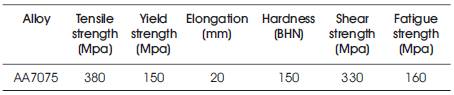
Table 3. Mechanical Properties
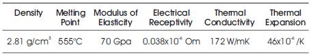
Table 4. Physical Properties
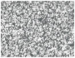
Figure 1. Microstructure of the Base Material AA7075 at 50X
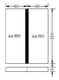
Figure 2. Plates Setup Before Welding
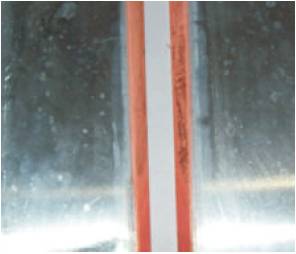
Figure 3. Copper Coated AA7075 Plates before Welding
The friction stir welding tool is made of high speed steel with 10% cobalt with a tapering pin. The tool is designed based on the briefly available literature and the tool proportions are decided in terms of the plate thickness to be welded. A software written in .NET and correlated with Solidworks will provide the proportions of the tool based on the plate thickness. This attempt is made in particular with special care to set the dimensions of the tool in standard relation with the thickness of the plates to be joined, so that best weld can be obtained by the future researchers. Friction stir welding was performed on the AA7075, 6 mm thick plates with and without copper coatings on the faying sides in optimum weld conditions. The copper coating on the faying sides of the work pieces enhances the temperature at the bottom side and there by improves the metal flow from advancing to the retreating side towards the formation of a good metallurgical bond. The workpiece samples were but welded in a FSW adapted vertical axis CNC milling machine with FANUC controller. The tool dimensions are tabulated in Table 5 and the corresponding tool design and drawing windows along with the manufactured tool are shown in Figure 4 and Figure 5 respectively. The welding process parameters used in running the experiments are optimized for AA7075 for maximum weld strength and maintained throughout the research as charted in Table 6. Simulation of the welding environment in Hyperworks 9.0 for the temperature distribution in the workpieces and tool has favoured the copper coated joints with safe and allowable temperature distribution limits as shown in Figure 6.
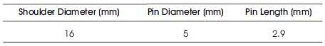
Table 5. Tool Dimensions
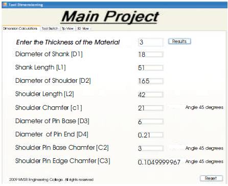
Figure 4. Design Window for the FSW tool
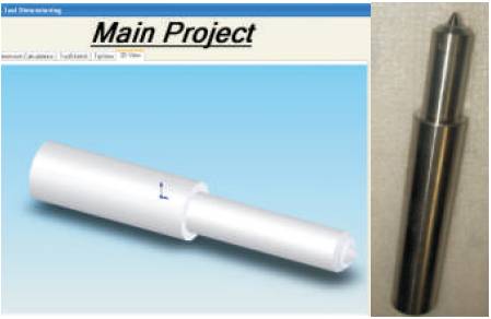
Figure 5. Solid Model and the Manufactured tool
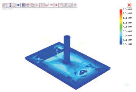
Figure 6. Temperature distribution in Hyperworks with Copper Coating
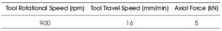
Table 6. Optimized Welding Parameters
The welded joints were tested for hardness across the weld direction as shown in Figure 7 and the obtained Vicker's Hardness Numbers (VHN) are tabulated in Table 7 and the corresponding graphs are plotted in Figure 8. The hardness profile across the weld direction for the weldments with copper coatings shows a smooth and gradual decrease from the base metal hardness to TMAZ, varies constantly from the advancing side of the weld with a smooth fall in the retreating side of the weldment with minimum being observed in the thermo mechanically affected zone. This uniform decrease in hardness is due to the reduction in temperature gradient by the heat provided from the bottom of the plates in the modified fixture. The hardness distribution for the weldments without copper coatings is observed to be similar with that of the weldments with copper coatings with erratic behaviour due to the presence of a steep temperature gradient that supports the flow resistance of the material at the bottom side accompanied by the difference in the tool rotation velocity vector and the tool feed direction vector.
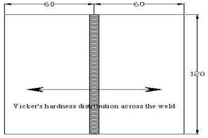
Figure 7. Hardness Distribution Across the Weld
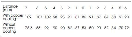
Table 7. Distribution of Vickers Hardness
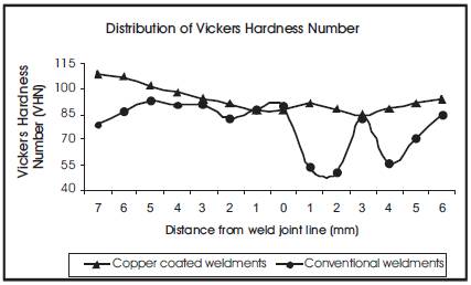
Figure 8. Vickers Hardness Distribution
The specimens for the tensile tests were prepared as per ASTM standard norms. E8 standard test specimens of gauge length 25mm has been extracted in longitudinal direction and transverse orientation of the weldment in WEDM machine from the conventional and copper coated weldments in Figure 9 to 11 respectively. The test samples were tested on a computer controlled Instron UTM at a crosshead speed of 1 mm/min, with hydraulic loading facility. The test results obtained for samples extracted across and along the weld direction for the weldments with and without copper coatings are tabulated in Table 8 and Table 9 respectively. The graphs plotted in Figure 12 and Figure 13 indicates the variation in tensile strengths for different weld conditions, along and across the weldments respectively. The obtained results show a considerable improvement in the joint strength in tension both along and across the weld direction for the joints made with copper coated weldments as compared to the conventional weldments made joint strength, backing the hardness results. This may be due to the reason that, heat from the bottom side is enhanced by the copper particles, thus making the metal flow phenomena equally in top and bottom sides thereby leading to a uniform and homogenous weld joint for superior tensile strength. The conventional joint lags tensile strength significantly as compared due to the inhomogenity in metal flow and reduced weld strength. From this observation, it is well thought-out that the tensile strength of the joint apparently depends on the metal flow and hardness distribution in the weld nugget.
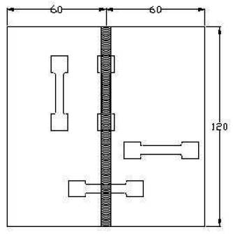
Figure 9. Sample Drawing and Specimens Extracted for Tensile Test
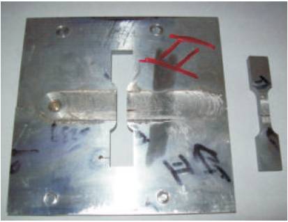
Figure 10. Conventional Weldment and Sample extracted as per ASTM Norms for Tensile test
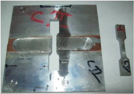
Figure 11. Copper Coated Weldment and Sample extracted as per ASTM Norms for tensile test
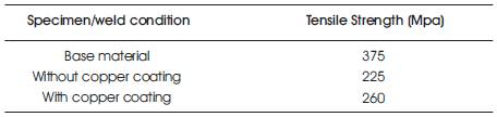
Table 8. Tensile Strength Across Weld Direction
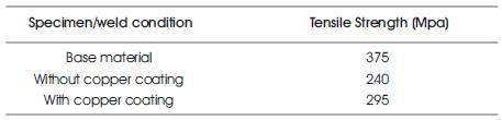
Table 9. Tensile Strength Along the Weld Direction
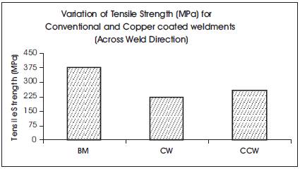
Figure 12. TS Comparison along the Weld Direction
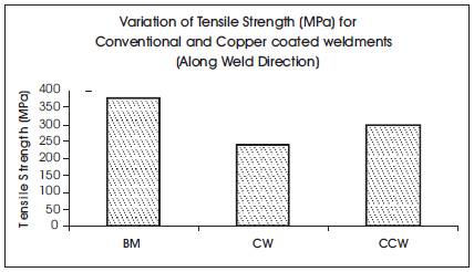
Figure 13. TS Comparison along the weld direction
All technical properties of materials are directly connected to their microstructures. The structure in the welding seam and its direct surrounding is strongly influenced by the uniformity in the pressure and metal flow during the friction stir welding process. The mechanically polished surfaces of the weldments were chemically etched with Kellers reagent to determine the microstructure of the welded aluminium alloys. Optical microscope with 20X magnification was used to identify the microstructures of the weldments and the structures of various zones are displayed in Figure 14 and Figure 15 respectively. There is very less variation in the macrostructure of the onion rings obtained in the joints made with the improved design fixture. Nevertheless, the microscopic structures of the joints with conventional fixture show considerable variation due to the inhomogeneous nature of the metal flow in the root part of the retreating side.
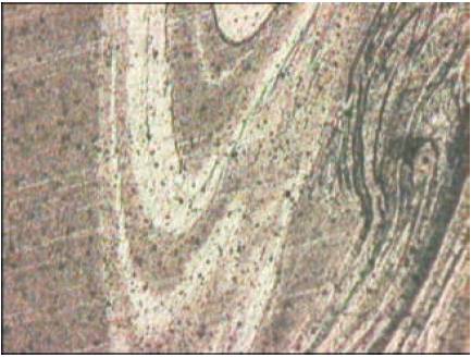
Figure 14. Weld zones in Copper Coated Joint
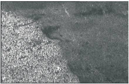
Figure 15. Weld CS of the Joint without Copper Coating
SEM analysis of the tensile tested fracture surfaces obtained from the weldments with copper coating in the weld zone as shown in Figure16 indicates the presence of long and large voids, small depressions, tear ridges, particle matrix de cohesion, all indicating the possibility of ductile failure. The fracture surfaces show wide distribution of microscopic voids revealing ductile behaviour of the welded joint before fracture. The SEM results of the conventional joints in Figure17 reveals kissing bond, in the fracture spot a clear indication of lack of frictional heat generated to form the nugget. Subsequently the metal around the tool could not infuse and ecrystallize, as it stucks to the each other leading to a kissing bond, a predominant factor for joint failure.
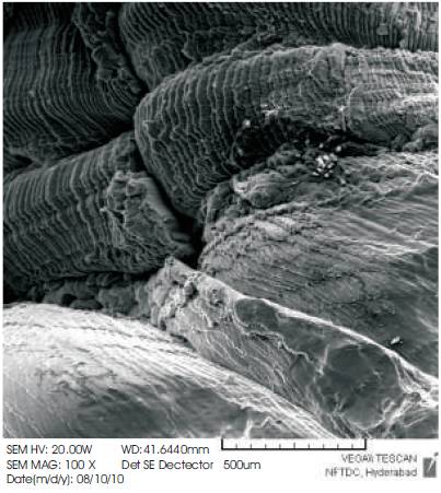
Figure 16. Fracture behaviour of the Joint without Copper Coating
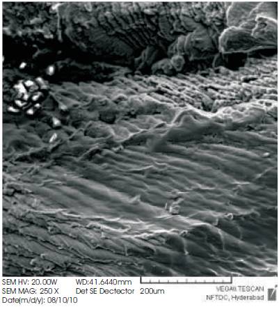
Figure 17. Fracture behaviour of the Joint with Copper Coating
The main aim of this research is to improve the weld strength by reducing the existing temperature gradient between the top and bottom surfaces of the conventional weld joints was successfully achieved, by introducing a copper coating on the faying sides of the weld plates. Mechanical and metallurgical investigations on the IMC formed exposed that a sound weldment in friction stir welding is possible by introducing a copper coating and thereby reducing the temperature gradient that exists with conventional joints.
The assessment of the mechanical properties suggests that uniform temperature and metal flow phenomenon for a mechanical stirring is the major flow mechanism in metallurgical bond formation. Comparison of the hardness and tensile properties of joints welded in the different fixtures show that the metal flow phenomenon is affected by the temperature gradient that exists in between the top and bottom surfaces of the weld joint. This temperature gradient is reduced by using copper coating technique for uniform and homogenous metal flow in the weld cross section thus leading to excellent mechanical properties as compared to the conventional FSW joints.