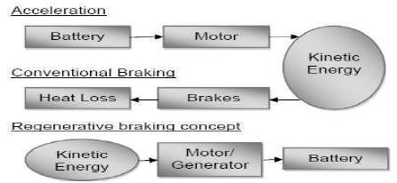
Figure 1. Energy Flow Overview
Regenerative braking is an effective approach for electric vehicles to extend their efficiency. It is the emerging technology used on hybrid gas/electric automobiles to recoup some of the energy lost during stopping. Regenerative braking has to be carried out together with the conventional barking. In brake system design for electric vehicles, the basic equation must be concerned, one is properly applying braking force to quickly reduce the vehicle speed and meanwhile maintain the vehicle traveling direction stable and controllable through the steering wheel on various road conditions and also recovering the braking energy as much as possible in order to improve the energy utilization efficiently. The regenerated energy is saved in a storage battery and used later to power the motor. Regenerative braking takes energy normally wasted during braking and turns it into usable energy. It does improve energy efficiency of the vehicle. In this work, a mathematical model of a regenerative braking system for the braking efficiency has been developed. The experimental results are compared with the simulated results. The electricity generated by the battery during braking varies accordingly to the speed of the vehicle. So to utilize the generated electricity completely a suitable Electronic Control Unit is designed.
Regenerative braking is an effective approach for electric vehicles to extend their efficiency. A few investigations have been made for regenerative braking and braking force distribution of electric vehicles [[1], [2], [3], and[4]]. It is the emerging technology used on hybrid gas/electric automobiles to recoup some of the energy lost during stopping. Regenerative braking has to be carried out together with the conventional braking. In brake system design for EVs, the basic equation must be concerned [5]. This energy is saved in a storage battery and used later to power the motor. Electric motors and electric generators are essentially two sides of the same technology.
In Regenerative Braking system, as the driver applies the brakes through a conventional pedal, the power supply to the electric motors is stopped. By this action, the motor stops propelling the vehicle but due to the forward momentum the vehicle moves for some distance and then eventually stops the vehicle[6].
Whenever the electric motor shaft is rotated (mechanical energy is given to the motor), it becomes an electric generator or dynamo [[7] and [8]]. This generated electricity is fed into a chemical storage battery and used later to power the car at city speeds. Regenerative braking takes energy normally wasted during braking and turns it into usable energy. Thus it improves energy efficiency of the electric vehicle.
The objective of this work is to implement the Regenerative Braking technology in electric vehicles particularly in Electric bikes. The first phase of the work is to develop a mathematical model and to simulate it using MATLAB/SIMULINK. A bike was selected for demonstration of Regenerative braking and the second phase is to implement the Regenerative Braking System in bike. A bike is selected for demonstration of Regenerative braking and also an ECU has been developed for optimization of the battery charging (Figure 1).
Figure 1. Energy Flow Overview
The Motor is selected by studying the various characteristics curves of motor and also by calculating the
If, Vmax is max velocity of the bike
Nmax is max speed of prime mover (motor)
g is Output driven to input driver ratio
r is effective wheel radius
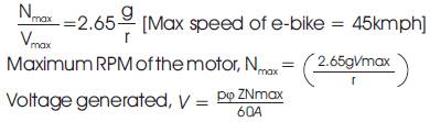
Ф = Flux / pole in weber.
Z = Total number of armature conductors
P = Number of poles
A = number of parallel paths (= 2)
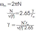
N = Speed of armature in rpm (Nmax of motor)

N is max speed of motor
From the Project specifications,
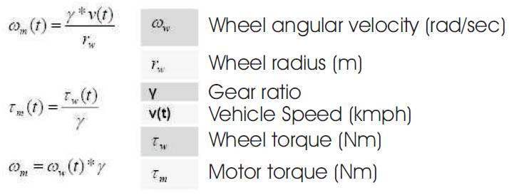
N =1200 rpm, rw = 0.31 m, v (t) =45 kmph
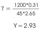
TW= no. of teeth in Wheel sprocket. (18 teeth)
TM= no. of teeth in motor output shaft
γ = (TW / TM)
TM= (TW /γ )
= (41/2.93)
=14 teeth (approx.)
Thus the output Sprocket of the motor should have 14 teeth to achieve maximum speed of 45kmph.
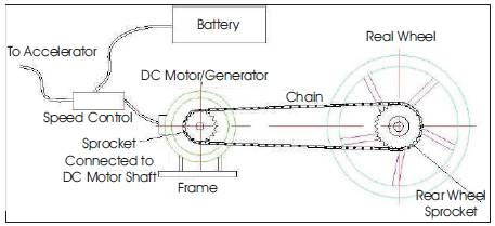
Figure 2. Model of Transmission System
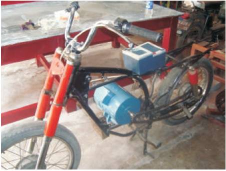
Figure 3. Experimental setup for RBS
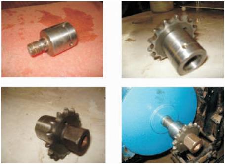
Figure 4. Flange that connects motor shaft and driveline system
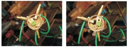
Figure 5. Contact breaker in driving and charging position
The experimental setup designed for the demonstration of regenerative braking in Electric bike is shown below.
In Regenerative Braking Technology, when the brakes are applied through a conventional lever, the current flow to the motor from the battery is stopped. Since there is no flow of current, the electric motor stops running thus stopping the bike. This regenerative braking is a mild brake which is due to the counter torque generated by the motor when it is converted to generator (Figure 6).
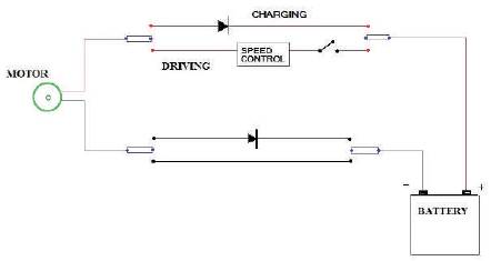
Figure 6. Working of RBS
Whenever the brake is applied, electric current supplied to the motor from the battery is cut down. Now the vehicle moves because of its forward momentum. Thus it rotates the motor and it act as a generator. Due to this, an emf is induced in the generator leading to the generation of electric current. This generated electricity is fed into a chemical storage battery and used later to power the bike at city speeds.
The circuit works in two modes
The driving circuirt consists of the terminals of the primover connected to the battery through a ON/OFF switch and a potential switch (Figure 7). These two switches are connected from the positive terminal connection of the battery. Potential switch is a component that controls the speed of the motor.
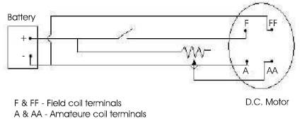
Figure 7. Driving circuit for RBS
The charging circuit has the diode which prevents the flow of current from battery to the motor due the reverse biased condition of diode (Figure 8). During generation mode the power from the generator is stored to a capacitor due to forward biased condition of diodes and it charges the battery. The electronic control unit for charging circuit is as given in Figure 9.
The layout for the optimized charging is shown in Figure 10.
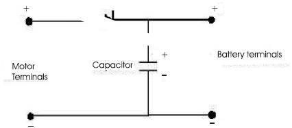
Figure 8. Charging circuit for RBS
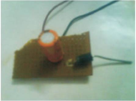
Figure 9. Electronic Control Unit for charging circuit
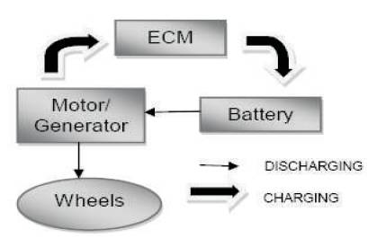
Figure 10. Layout for optimized charging
| Drag force Fd - (½)CdρAV2 | [1] |
 Cd = Vehicle aerodynamic drag coefficient
ρ = Air density, Kg/m3
A = Vehicle frontal area, m2
V = Vehicle velocity, m/sec
| Rolling resistance, Fr = MgCr | [2] |
M = Vehicle test mass, Kg
g = Acceleration due to gravity, m/sec2
Cr = Rolling resistance coefficient
| Acceleration force, Fa = Ma | [3] |
M = Vehicle test mass, Kg
a = Vehicle acceleration, m/sec2
Total power needed to propel the vehicle,
| P = (Fd + Fr + Fa ) V | [4] |
Total energy required, E = ∫ P dt
Case (i) when a ≥ 0 (vehicle is accelerating)
Ew = ∫ Pt dt
Ew = Energy output at the driving wheels
Pt = Power at instantaneous time t
E1 = Ew / η1
E1 = Energy input to the power train
η1 = Overall efficiency of the power train system
Case (ii) when a ≤ 0 & P ≥ 0 (vehicle slows down or braking)
Battery is still supplying energy to maintain the vehicle velocity
Ew = ∫ Pt dt
Ew = Energy output at the driving wheels
Pt = Power at instantaneous time t
E1 = Ew / η1
E1 = Energy input to the power train
η1 = Overall efficiency of the power train system
When a ≤ 0 & P ≤ 0, the regenerative braking is activated.
Vehicle kinetic energy is converted to electrical energy which is returning to the battery.
Er = - ∫ Pt dt
E2 = Er / η2
Where Er = Energy regenerated
E2 = Energy returned to the electric storage system
η2 = Overall efficiency of the regenerative system
E2 / E1 express the percent of regenerative energy returning to the vehicle electric storage system.
E1 expresses the energy consumption of the vehicle without regenerative braking system.
U = initial velocity
V = final velocity
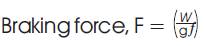
W= Weight of the vehicle
F = retardation
t = braking time or stopping time
g = 9.8 m/s2
By Newton’s equations of motion,
V = u - ft [Once brake is applied V=0]
ƒ = u / t
V2 = U2 - 2ƒs
U2 = 2ƒs
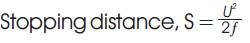
(When the vehicle moves on a level road)
Work done = Braking force x Distance moved
Work done = Heat generated
Heat generated = 
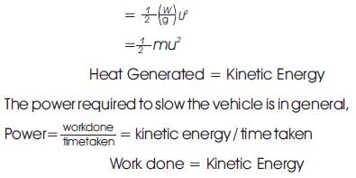
But here, it is calculated by
Pwh = vehicle velocity * Driving force
| = ν * FT | [7] |
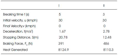
Table 1. Calculated values of Mathematical Equations Governing Regenerative Breaking System under two cases
The heat generated is independent of braking time (i.e.) how long the brakes may be applied the kinetic energy wasted is constant.
Regenerative Braking system can reduce the stopping distance considerably than the conventional systems.
The electric bike is tested for its battery discharge rate. The vehicle was run on the chassis dynamometer to measure the battery discharge rate by subjecting it to numerous frictional brakes at various speeds. Then the regenerative braking system is used and similar tests are conducted to find the improved performance in the battery discharge time (Figure 11).
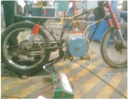
Figure 11. Testing the E-bike on chassis dynamometer
Also using the chassis dynamometer, the voltage generated at various speeds and the stopping distances are measured. Finally the efficiency of regenerative braking technology is calculated from the recorded values and the following characteristic curves are drawn.
The D.C motor is tested without any load to find its generated voltage at various speeds and the readings are tabulated. Then the motor is fitted in the bike for applying regenerative braking system in it and tested in the chassis dynamometer and the graph is plotted for generated voltage at various speed of the bike and it is shown in Figure 12.
From the result, it is inferred that the amount of voltage generated at low speed is less when compared to that of higher speed of the vehicle. As the speed of the vehicle increases, the generated voltage also increases and it is very high at the maximum speed of the bike.
The bike is driven at various speeds on the chassis dynamometer and their respective stopping time or regeneration period are measured by applying the regenerative braking i.e by cutting down the supply to the motor. The deceleration of the vehicle is calculated for each stopping distance and the graphs are drawn in Figures 13 & 14.
The stopping time or regeneration period increase with the increase in the vehicle speed. The bike takes more time to stop at higher speeds when compared to lower speeds. This is because the velocity of the vehicle will be higher at high speeds.
The vehicle is driven for various speeds on the chassis dynamometer. First the bike is driven without RBS by applying numerous brakes during operating period. Then the bike is driven with RBS by subjecting it to the same number of braking (Regenerative braking). The battery discharge rate is measured for both the cases. The graphs are shown in Figure 15.
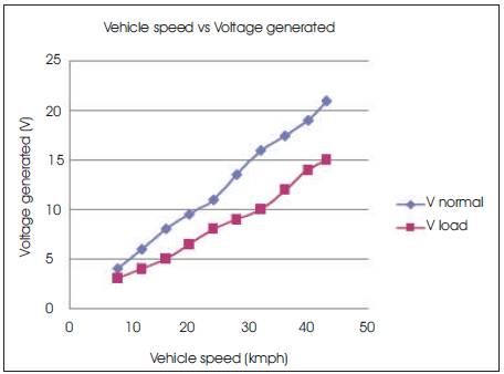
Figure 12. Voltage generated for various vehicle speed
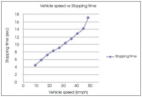
Figure 13. Variation of stopping time (regeneration period)with vehicle speed
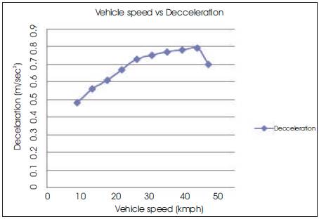
Figure 14. Deceleration of the vehicle with vehicle speed
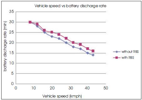
Figure 15. Comparison of Battery discharge rate for variousspeed with and without RBS
Battery discharge rate is maximum at high speed of the vehicle and as the speed of the vehicle decreases the discharge rate also decreases. With the application of regenerative braking technology, there is a significant improvement in the battery discharge rate.
The improved average efficiency for the discharging time of the battery in both cases (with and without RBS) with respect to speed is calculated as follows.
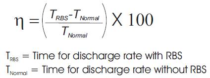
Average calculated efficiency of the electric bike with regenerative braking system with respect to the speed is 9.05%
From the results, it is found out that the voltage generated at high speeds is more and the battery discharge rate is improved by Regenerative braking. The efficiency of the battery is increased by 9.05% and it is further increased twice in sloppy areas. Also, an ECU has been developed to utilize the voltage whole generated through RBS to charge the battery. Moreover when applying regenerative concept, the accompanying friction (electrical resistance) assists the normal brake pads in overcoming inertia and helps slow the vehicle.
From the result, it is found that the generation of voltage is high at high speeds. So, the efficiency of regenerative braking is more at high speed than at the low speed. To improve the efficiency of the bike at low speed, an ECU is developed for optimized charging (Figure 16).
From the Figure 17, it is inferred that the discharge time of the battery decreases as the speed of the bike increases. It is because the flow of current to the motor is more at high speed than at the lower speed.
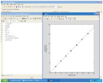
Figure 16. Simulation of Voltage generated

Figure 17. Simulation of Discharge time of the battery
1. The main issue with regenerative braking is that it still relies on friction braking too.
2. Consequently the friction brake is still necessary to bring the vehicle to a complete halt.
3. Efficiency of Regenerative braking at lower speed is less.
| EVs | Electric vehicles |
| RBS | Regenerative Braking System |
| D.C | Direct Current |
| h.p | Horse Power |
| rpm | Revolution per Minute |
| V | Voltage |
| I | Current |
| T | Temperature |
| A, amps | Ampere |
| AH | Ampere Hour |
| ECU | Electronic Control Unit |