
Figure 1. QR Code
A QR code is a type of barcode that can hold more information than the familiar kind scanned at checkouts around the world. The “QR” stands for “Quick Response”, a reference to the speed at which the large amounts of information they contain can be decoded by scanners. They are being widely used for advertising campaigns, linking to company websites, contest sign-up pages and online menus. In this paper, we propose an efficient module to extract QR code from background and solve problem of rotation in case of inaccurate image taken from mobile camera.
A QR Code is a specific matrix barcode (or twodimensional code), readable by dedicated QR barcode readers and camera phones. The code consists of black modules arranged in a square pattern on a white background. The information encoded can be text, URL or other data.
Common in Japan, where it was created by Toyota subsidiary Denso-Wave in 1994, the QR code is one of the most popular types of two-dimensional barcodes. QR is the abbreviation for Quick Response, as the creator intended to allow its contents to be decoded at high speed [1].
QR code is a 2D matrix barcode. Each module corresponds to a bit. A black module and a white module represent '1' and '0' respectively. Figure 1 illustrates the structure of the QR code [2].
QR Codes consist of different areas that are reserved for specific purposes. In the following we refer to version 2 of QR Codes Figure 2, because version 1 does not contain all patterns [3].
Finder Pattern: The finder pattern consists of three identical structures that are located in all corners of the QR Code except the bottom right one. Each pattern is based on a 3x3 matrix of black modules surrounded by white modules that are again surrounded by black modules. The Finder Patterns enable the decoder software to recognize the QR Code and determine the correct orientation.
Separators: The white separators have a width of one pixel and improve the recognizability of the Finder Patters as they separate them from the actual data.
Timing Pattern: Alternating black and white modules in the Timing Pattern enable the decoder software to determine the width of a single module.
Alignment Patterns: Alignment Patterns support the decoder software in compensating for moderate image distortions. Version 1 QR Codes do not have Alignment Patterns. With growing size of the code, more Alignment Patterns are added.
Format Information: The Formation Information section consists of 15 bits next to the separators and stores information about the error correction level of the QR Code and the chosen masking pattern.
Data: Data is converted into a bit stream and then stored in 8 bit parts (called codewords) in the data section.
Error Correction: Similar to the data section, error correction codes are stored in 8 bit along codewords in the error correction section.
Remainder Bits: This section consists of empty bits if data and error correction bits cannot be divided into 8 bit codewords without remainder.
Figure 1. QR Code
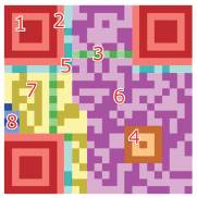
Figure 2. Structure of QR Code Version 2
The capacity of a QR Code depends on several factors. Besides the version of the code that defines its size (number of modules), the chosen error correction level and the type of encoded data influence capacity [3].
Version: The 40 different versions of QR Codes differ mainly in the number of modules. Version 1 consists of 21x21 modules, up to 133 (lowest error correction level) of which can be used for storing encoded data. The largest QR Code (Version 40) has a size of 177x177 modules and can store up to 23,648 data modules.
Error Correction Level: There are four levels as shown in Table (1) of error correction that can be chosen by the user at creation time. Higher error correction levels increase the percentage of codewords used for error correction and therefore decrease the amount of data that can be stored inside the code.
Encoded Data: QR Code can use different data encodings. Their complexity influences the amount of actual characters that can be stored inside the code.
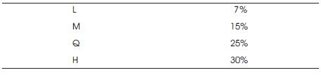
Table 1. Error Correction Level
In this section, the recognition module of QR Code is introduced, which is performed by using MATLAB® version R2012a, abbreviation of matrix laboratory, which is a highlevel language and interactive environment that enables to perform computationally intensive tasks faster than the traditional programming languages such as C, C++, and Fortran. Also have many key features like: High-level language for technical computing, Development environment for managing code, files, and data, Interactive tools for iterative exploration, design, and problem solving, Mathematical functions for linear algebra, statistics, Fourier analysis, filtering, optimization, and numerical integration, 2-D and 3-D graphics functions for visualizing data, Tools for building custom graphical user interfaces and Functions for integrating MATLAB based algorithms with external applications and languages, such as C, C++, Fortran, Java, COM, and Microsoft® Excel® [4]. The module consists of several steps as shown in Figure 3.
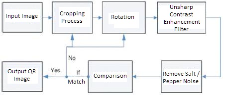
Figure 3. Module Steps
The Input image is an RGB color image which is captured by mobile phone. The QR code imbedded in the image must have a specific size.
After assuming specific dimension for QR Code, the cropping process will take this dimension and crop the input image. Every time the matching is not achieved (will be described later), another cropped image will be taken from the input (original) image.
The image taken from mobile camera may have rotation, so this must be fixed to get clear QR Code. An example for rotated point (x,y) by an angle Ɵ is shown in Figure 4, with the rotation equation eq (3.1).
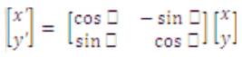
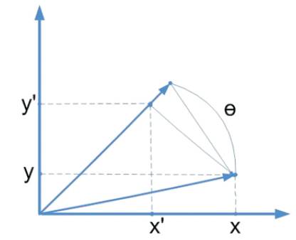
Figure 4. Rotating point (x,y) by an angle
The original image acquired using a digital camera is not always clear because of various factors such as intensity variation, distance of the object from the camera, etc. Several image enhancement techniques are used to sharpen or enhance the visibility or clarity of the image. Contrast enhancement is one of the popular ways to increase the visibility of a digital image. In contrast enhancement intensity values of the pixels in the whole image are modified to increase the visibility. There are several contrast enhancement techniques. Unsharp filtering or masking is one of the popular ways of image sharpening [5].
Unsharp filtering operates by subtracting a smoothed (or unsharp) version of an image from the original in order to emphasize or enhance the high-frequency information in the image (i.e. the edges). First of all, this operation produces an edge image from the original image using the following methodology:

The smoothed version of image is typically obtained by filtering the original with mean or Gaussian filter kernel. The resulting difference image is then added onto the original to affect some degree of sharpening:
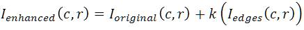
Using a given constant scaling factor k, ensures the resulting image is within the proper range and the edges are not (oversharp) in the resulting image. Generally, k = 0.2 to 0.7 is acceptable, depending on the level of sharpening required. It is secondary stage that gives rise to the alternative name of boost filtering [6].
The resulting image can be contaminated by salt/pepper noise during the conversion process or during data acquisition such as scanning. This appear as randomly distributed black dots on a white background and white dots on a black background component, each noise dots can be either an isolated pixel or composed of more than one pixel. Noise removal is very important preprocessing to facilitate other subsequent operations [7]. The difficulty in removing salt/pepper noise from binary image is due to the fact that image data as well as the noise share the same small set of values (either 0 or 1) which complicates the process of detecting and removing the noise. This is different from grey images where salt/pepper noise could be distinguished as pixels having big difference in grey level values compared with their neighborhood [8].
In this module, and after making rotation on image, the edge of black dotes in QR code may be changed in its shape and new salt/pepper noise will appear. Benefiting from sharp filter and small module which consist of comparing the image with rotated white image and by making the following conditions on the image pixels: if pixels match, keep it 255, if it's between 245 and 10, also make it 255 and else 0, as a result pepper around edge will be reduced, in its turn will help error correction level.
After cropping and rotation process is performed, a comparison method will compare the resulting image (input image after cropping and rotation) with index image, this method will benefit from (Finder Pattern) which was described before. If the comparison matches the case, then the resulting image is the required output image, if not then another rotation degree and cropping pixel will be taken until the case is matched.
The output or resulting image is a clear QR code which could be recognized by code reader. After entering three different images in (size and rotation degree), clear QR codes will be produced as shown in Table 2, which clarifies the main steps – cropping and rotation-in module.
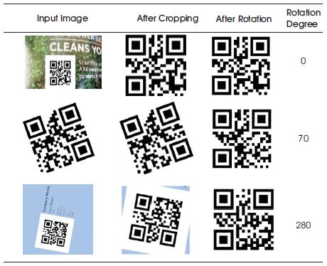
Table 2. Experimental Results
In this paper, the authors proposed a module for cropping and rotating QR code from an image. This module uses the property of QR code especially “the finder pattern” to find the code location. Also this paper analyzes and presents a quick and easy algorithm on focal point for extraction and rotation of QR code especially if the image taker tries to focus on QR code. Proposed module solves the transformation problems in rotating space on the barcode image geometric distortion correction. The experimental results showed the effectiveness of the proposed module especially for recognizing QR-codes and rotation with very low error percentage.