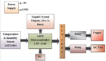
Figure 1. Block Diagram of IEMCS
High performance digital computing devices like advanced microcontroller, plays vital role in the field of industrial and instrumentation electronic to control various physicochemical parameters. Among the various physicochemical parameters, humidity and temperature are important in the industrial process and controlling these parameters is critical. Therefore, this paper presents the ARM microcontroller based embedded system developed to control the physicochemical parameters. Utilizing the promising features of the ARM7 LPC2148 microcontroller, a prototype is developed to monitor and control the humidity and temperature. The resistive humidity and temperature smart sensor AMT1001 is interfaced with ARM7 to achieve the objectives. The digital readout is integrated in the design using the smart LCD module. The humidity and temperature are controlled with a fogger and a cooling fan which connected to the control unit through a relay. The firmware is developed in embedded C using Keil μVision5 IDE. The system under the investigation is calibrated as relative humidity in percentage and temperature in degrees centigrade. The paper discussed the design, development and implementation of the prototype along with the interpretation of the results under investigation.
The main objective of the present research work is to design an embedded system for monitoring and controlling of the various industrial process parameters. The availability of controlled environment is must for process industries like petroleum refining, petrochemicals, sugar, fertilizers, semiconductor manufacturing, paper, pharmaceuticals, distilleries, etc. A set of processes and actions are needed in the process industry and they must be monitored and controlled to maintain the quality environment. The various parameters including humidity, temperature, concentration of different gases in air, determines the quality of the environment. The temperature and humidity are the two parameters that need to be precisely monitored. Industrial automation and process controls increases the effectiveness of a process industry (Kumari & Sailaja, 2014). For an efficient industrial processes, controlling various parameters is a challenging task and needs a complex network. A manual system is less accurate and requires a lot of attention and care (Ramyateja & Kishore, 2016). To cater all these needs, a portable Industrial Environment Monitoring and Controlling System (IEMCS) project is under development. This paper discusses the design and development of humidity and temperature control module for project IEMCS.
On survey it is found that the various temperature and humidity sensors are readily available. Among comparative study, it is observed that, the integrated temperature and humidity sensor AMT1001 module is available with features of high accuracy, high reliability, and consistency with longterm stability (Elaydi, 2017). The sensor features long distance transmission so that, the signals need not to be conditioned over long distances. The sensor can be used for application in HVAC air conditioners, humidifiers, dehumidifiers, and has extended the range to environmental monitoring, industrial process control, agriculture, measuring instruments, etc. Therefore, it is exclusively selected for the present system.
The microcontroller based embedded system design is a highly suitable technology for the development of instrumentation for precise and reliable measurement of physical quantities such as humidity, pressure, temperature, etc. (Kumaravel et al., 2010). System on Chip (SoC) concept is being widely used with microcontroller embedded technology for designing process control instrumentation (Tilekar et al., 2017). Therefore, microcontrollers are attracting the research enthusiasts who sought to develop smart embedded systems. The ARM7 series microcontroller LPC2148 is suitable for the present objective as it simplifies the complex hardware design and firmware development. The microcontroller LPC2148 with several in-built features and on-board peripherals is at the core of the present system.
The embedded system covers the idea of integrating the hardware and software. Choosing the hardware components of the system has an effect on the result or outcome of the system (Pote et al., 2021). Figure 1 shows the block diagram of the proposed system. The hardware, in first place, deals with the process of interfacing various on board and off board peripherals to the ARM LPC2148 core. As could be observed in Figure 1, the on-board driver ULN2003 drives the control signals to the relays.
Figure 1. Block Diagram of IEMCS
The circuit diagram of the system is shown in Figure 2. Circuit diagram gives the clearer view of wiring among the peripherals. The LPC2148 works with the 4 MHz clock frequency. The sensor AMT1001 provides two analog outputs for temperature and relative humidity that are provided to first two sequential analog input channels of microcontroller. Mostly, LCDs (Liquid Crystal Displays) are used for displaying the calculated parameters in embedded systems (Venugeetha et al., 2020). The continuous digital readout of the parameters is done with use of smart LCD and through the virtual terminal as well. The ULN2003A drives the control signal from core to the pair of relays. The fogger or mist maker and cooling fan are driven according to the control signal in order to reach the expected figures for respective parameters.
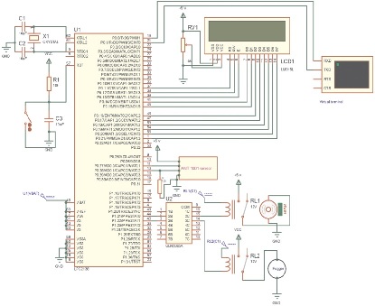
Figure 2. Circuit Diagram of the System
The sensor AMT1001 generates the output signal for relative humidity corresponding to the water droplets gathered on its inner surface. It also generates another output signal for the sensed heat. Microcontroller ARM LPC2148 performs operations like analog to digital conversion, arithmetic operations, etc. According to the parameter values the control signals are generated. ULN2003 drive relays according to the control signal to control actions of fogger and fan. If the relative humidity is below the set limit then fogger is turned on and cooling fan is turned off. If the humidity crosses the set value then the fogger is turned off and cooling fan is turned on.
The LPC2148 ARM7TDMI microcontroller comes with 512K on-chip flash memory. LPC2148 is RISC based processor that uses fewer transistors than other typical processors. Hence it leads to low cost and low power consumption (Gandotra et al., 2017). It is ideal for developing embedded systems involving high speed applications, and for monitoring and controlling real time data. It has inbuilt 10 bit ADC, and UART based serial communication and is well suited for application requirement (Lavanya & Babu, 2017). The features of LPC2148 are enlisted below.
Multiple serial interfaces including two UARTs, two Fast I²C-bus (400 kbit/s), SPI and SSP with buffering and variable data length capabilities.
The 4 terminal, compact, integrated relative humidity and temperature sensor AMT1001 works with 4-5.5 V DC (Figure 3). It provides outstanding accuracy over the entire range of 20% to 90% RH. The sensor gives analog output in the form of voltage for the relative humidity. The sensor typically provides 0.6 to 2.7 V output for above mentioned operating range of relative humidity. The Figure 4 shows the graph of ideal output voltage for relative humidity provided by manufacturers.
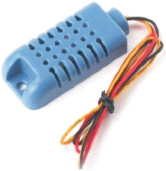
Figure 3. AMT1001 Sensor
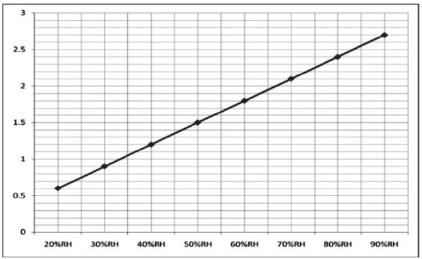
Figure 4. Graph of Ideal Output Voltage for Relative Humidity
The temperature sensing element used in AMT1001 is NTC10K thermistor. The thermistor has a sensing range of - 40 ~ 125 0C. The sensor is capable of providing reliable output for a temperature range 0 ~ 50 oC. As could be observed in circuit diagram a 10 kΩ resistor is connected across the temperature out of AMT1001 sensor. It converts the change in resistor type output of sensor for temperature to change in voltage which is then provided to ADC 0 channel 1(pin 0.28) of microcontroller.
ULN2003 are used for driving a wide range of loads including solenoids, relays, DC motors etc. It has 7 Darlington transistor array. Each transistor can sink current up to 500 mA. In the present system the ULN2003 drives the relay which drives the mist maker and fan.
The accuracy of the relay depends upon its components. The relay used here in the system is of SPDT type relay operating with a DC +9 volt supply. The electrical stimulation is input signal to the relay. It converts the actuating input signal into an electromagnet. The electromagnet, in this type of relay, breaks NC (Normally Close) contacts.
Ideally, the thermistor element in sensor for sensing the temperature provides the output with the change in resistance. In the present system, for convenience, the voltage is changed by connecting a 10 kΩ resistor to the output terminal. The calibration process is carried out for a wide range of temperatures and calibrated against ideal thermometer. The calibration setup of system is shown in Figure 5.
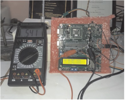
Figure 5. System Setup for Calibration of Temperature Measurement
To carry out the calibration process both the temperature sensitive point of the standard thermo meter and sensing part of AMT1001 sensor are placed inside a heater box containing a high voltage light bulb. The analog output of the temperature is displayed on second line of LCD as well as on standard digital multimeter for verification. The calibration as observed in Equation (1) is obtained by the temperature reading chart shown in Figure 6 and is used for further calculations.
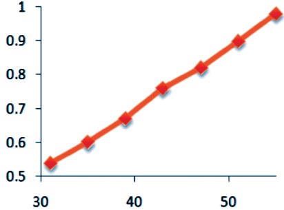
Figure 6. Calibration Graph for Temperature
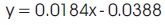
For calibration of system for relative humidity, the sensor is placed inside humidity chamber manufactured by 'GAYATRI scientific' in nearby place of the sensor of chamber as shown in Figure 7. The proportional voltage generated by sensor for respective relative humidity generated inside the chamber for a range of 25% RH to 90% RH. On observation of voltage readouts, it is found that, the system gives output nearly equal to ideal output voltage provided by manufacturer of sensor as depicted in chart of Figure 4, for a range of 50% RH to 90% RH. The calibration graph plotted is shown in Figure 8. The calibration as observed in Equation (2) is obtained from graph and is used for further calculations.
Figure 7. System Setup for Calibration of System for Relative Humidity Measurement
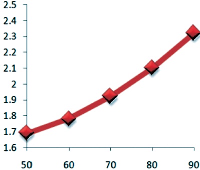
Figure 8. Calibration Graph for Humidity
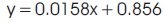
The development of an embedded system cannot do without the software part. The software is indeed the part that plays key role in the success of the system. For the present control system, the software is developed in embedded C in popular IDE (Integrated Development Environment) Keil μVision5. Keil μVision5 is chosen due to its debugging feature (Lavanya & Babu, 2017). Figure 9 shows the flow chart of the firmware. After declaring the essential global variables, the various functions are written in accordance with peripheral requirements. Globally declared functions are required for synchronized communication between peripheral devices. Global functions include functions required for LCD operations, delay routines and serial communication, etc. The ADC is triggered to convert the analog voltage supplied by the sensor to digital data. The respective relative humidity and temperature values are obtained from the calibration equations. The control limits for both parameters are set to turn on or turn off fan or fogger. If relative humidity is below 50% RH then fogger is turned on and once it is above 70% RH then the fogger is turned off. If temperature is above 15 0C then fan is turned on and once temperature is cooled down to 10 0C then the fan is turned off. After successful debugging of the firmware, the generated hex file is loaded into the flash memory of the microcontroller using the bootloader.
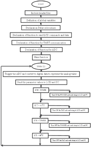
Figure 9. Flow Chart of the Firmware
Figure 9. Flow Chart of the Firmware
The designed prototype is implanted in the humidity chamber in our laboratory to observe parameters controlled by the system. The sensor is implanted at the place close to the sensing unit of the chamber. The standard humidity chamber has two displays for relative humidity and temperature readout. As can be observed in Figure 10, the relative humidity of the chamber is set to 90% RH and temperature is set to 25 0C. The red figures indicate the temperature and relative humidity inside the chamber at that instant. Smart LCD implanted in the present system displays the relative humidity sensed by the sensor which is close to that of chamber.
The system is then tested for the set control actions. The system, as per the control actions, turns on and off the fogger as well as cooling fan and sends message accordingly regarding to the same to the PC along with the parameter readouts for real time monitoring and controlling.
Figure 10. Implementation of System at the Humidity Chamber
It is concluded that, the system is precisely calibrated for the two vital industrial process parameters, i.e. relative humidity and temperature. The system has met its goal of establishing an automated system for controlling humidity and temperature parameters with implementation of fogger and cooling fan at the control unit. Moreover, the conditions or environment inside the humidity chamber is simulated to that of industrial atmosphere. Hence, it can be concluded that, the control system is ready for implementation at the actual industrial process control unit. The system could work with high reliability and accuracy without human interface which in turn will reduce the necessity of manpower at the control unit.