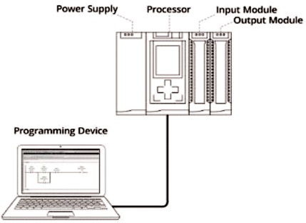
Figure 1. PLC with Hardware Component
Programmable Logic Controller (PLC) plays vital role in many areas ranging from household system to complex Industrial control applications. PLC is one of the cost effective tool for many industrial and commercial automation application when compared with Human Machine Interface, SCADA, DCS and Robotics. This paper presents review on the role of PLC in different areas. It also highlights architecture, interfacing and programming of PLC. Application of the PLCs in various areas are also reviewed in this paper.
The worldwide control and automation business is likely to expand from 151 billion to 230 billion USD in coming four to five years. This hike of business in market can be associated with recent development in the technology tools, optimization of product and needs of society. The increased need of automation in various fields attracts to the use of PLC as automation tool in various industrial and commercial applications. Mass production in manufacturing sector needs the automation to fulfill the requirements of the increasing population without compromising the quality, cost and time constraint. In recent years the attentions towards restructuring of systems also attract automation tools to use in various commercial applications such as elevator systems. PLC market cost is likely to increased from 11 billion to 16 billion USD in coming five years.
Advance operating digital electronic tools uses a memory that can be programmed and also provides storage space for instructions. Numerous functions considered are time based counting, timer and regulating arithmetic functions. Digital devices execute the instructions and it interact with the various processes through digital and analog types of modules. Digital modules operate based on the discrete modes operations such as digital logic. In comparison to this, analog modules operate on continuous mode. PLC control the modules in the DCS and SCADA systems. PLC becomes prime element in many small scale applications as compared to other automation tools because of their size, ease of operations and interfacing capabilities.
Leading PLC manufacturer are Bosch Rexroth, ABB, Eaton, Fuji Electric, KEYENCE, Koyo Electronics, IDEC, Panasonic, Yokogawa, Toshiba, Mitsubishi Electric, Rockwell Automation, OMRON, Schneider Electric, and Siemens. Manufacturers are continuously upgrading the technology and investing to enhance the tools and provide the customized solution to end users. PLC is playing the role of industrial computer, which provides robustness and is widely used to control production process and manufacturing plants. Many process such as conveyor systems, filling plants or operation require greater reliable system, use of programming, safety interlocks, more accuracy and fault diagnostic functions.
Figure 1 shows basic blocks of PLC. It consists of the hardware components: microprocessor, power supply, I/O modules and a programming terminal or instrument. The input power supply is 230 V AC. Output of this power supply is DC; generally all the modules require the DC power supply (Petruzella, 2005).
Figure 1. PLC with Hardware Component
The modules are connected to discrete or continuous field instrument. Input devices are input switches, push buttons, encoders, relays and transmitter output. Output devices are relays, lamps, motor starters and solenoid valves. Use of digital input and output are required by number of devices, few of them directly interfaced to PLC, i.e., pushbuttons, relays, etc. Normal voltage ranges are 0-230 V AC and 0-24 V DC, where 24 V DC and 230 V AC is normally considered high level or ON condition and 0 V considered as low level or OFF condition. In many of condition, voltage falling below the 2 V is considered as zero and voltage level above 22.5 V is considered as one or high. In continuous mode of operation, the dimmer switch is used to vary the output continuously with respect to continuous change in input (Kilian, 2001). Latest dimmer switches have been advanced to be more effective.
The processor consists of the CPU (central processing unit) and memory. The processor section makes the decisions necessary to distinguish and handle field devices integrated in I/O modules. Microprocessor, based on programmed controls allow arithmetic operations, logical functions, memory exchange, hardware interface, networking and related functions, etc.
Programming terminal in today's industrial applications is usually desktop industrial computer that helps in programming and to upload decision-making programs for the PLC application. In most of cases, the programming devices are advanced handheld portable terminal to enable tthat allows users a hassle free work.
The architecture deals with hardware and software elements, design specification and communication among them, resulting in PLC based application. PLC architecture is similar to the standard computer system architecture. PLC architecture varies and depends on work reliability, capabilities to work in hazardous environment, number of input and output handle, and interfacing peripherals. In general, fixed PLCs are used for micro to small scale and less complex applications. For medium sized typical application, modular PLCs are used. They PLCs are applicable for high scale and complex applications (Michel, 1990).
Fixed type PLC is single unit architecture. All the hardware parts are assembled in one unit. Hardware parts, i.e., power supply, processor, memory and input output communication interfaces are integrated with the fixed PLC. Fixed type of PLCs is also called as micro, mini or basic PLCs as shown in Figure 2. Some common PLCs by different manufacturer are:
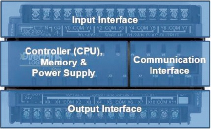
Figure 2. Fixed Type PLC Architecture
Nowadays, fixed PLC is assembled with wide range options such as high speed processors, advance terminals and network capacities that can be mapped with another type of PLC architecture helping to reach numerous industrial and commercial applications.
In modular type of PLC architecture as in Figure 3, a separate module for input and output with the hardware block is connected in series to fit in racks. The rack type may be utilized for various sizes of controllers and it has functional blocks. Each block is connected using common mounting platform which has provision to add more blocks in it. Therefore, modular PLCs can be configured for different applications. Allen-Bradley PLC-5 PLC of Rockwell automation is modular type PLC.
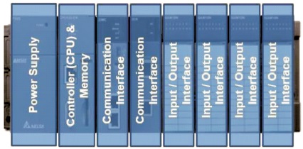
Figure 3. Modular Type PLC Architecture
A PLC module is intended with specific function in association with the architecture. Primary elements used in PLC are microprocessor, power supply module, input and output, communication interfacing modules. Design of modular PLC varies from manufacturer to manufacturer and cannot be interchanged. Modular types are generally preferred in high performance process and large number of input and output devices are interfaced. Modular PLCs are used in applications like manufacturing process, food processing, and mining industries, as this applications requires more number of input and outputs and handle digital as well as analog inputs/outputs. This type also performs the proportional-integral-derivative control actions. Modular PLCs is particularly designed to provide medium to high level automation projects. Benefits of this type of PLC are large storage, large numbers of digital and analog input and output, good communication facility, easily expandability. Some commercially available modular PLCs are:
Distributed PLC is high performance modular architecture system with capability to communicate with different types of hardware sub systems situated at various point through high speed communication channel.
Individual terminal in the distributed PLC system contains number of hardware subsystems that are installed in a integrating system called a node, rack or drop, as shown in Figure 4. Each terminal (drop), a node or rack in the distributed PLC system must have a interacting module and can either contain a PLC with input and output (I/O) modules or just I/O peripherals. When only there is a communication point without PLC processor module and just input and output module are utilized, then the node is called distributed input or output.
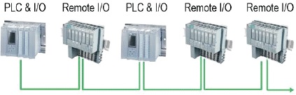
Figure 4. Distributed Type PLC Architecture
Distributed PLCs are intended for large turnkey projects as they are not limited to physical location. They permit the hardware elements to be situated at different locations by using high speed interfacing channels to interface the processors and distributed I/O. The distributed PLC type is viewed to be a site broad process control solution. The major differences between distributed PLCs and other types of PLCs is that they contain high performance processors, large memories and are able to work with large numbers of I/O, use higher level programming languages and can drive large amounts of complex process control tasks. Some commercially available distributed PLCs are:
This type of communication is when bit words are concurrently transfered through parallel cables. This permits data transmission to small distance with high speed. This type can be used when PLC interface with laboratory devices. Parallel type communication is used in accordance with the standard IEEE 488.
Serial data transmission takes place as a single bit pattern at a time. When data is transmitted, word is converted into single bits and when received, they reform into word form at receiving point. This type of communication is preferred when data is to be transmitted to long distance. It uses the serial connection between a desktop computer and a PLC. RS232 communication interface is preferred for serial communication with external devices. Other type of interface such as RS422 and RS423 are also used for long distance communication using cables with higher transmission rates.
Common types of PLC Programming Languages:
Ladder diagram is simple wiring diagram generally used for electrical circuits Ladder programming basically modeled from relay-logic. It uses the physical modules such as relays and switches to regulate the process (Clark, 2018).
Ladder diagram is prepared in the form of horizontal rungs with two vertical lines that represent the electrical connection. With help of such diagram, power supply for the circuits is always shown as two vertical lines with the rest of the circuit as horizontal lines. The power lines, or rails as they are often termed, are like the vertical sides of a ladder with the horizontal circuit lines like the rungs of the ladder.
It is used for pictorial representation of system operation to show the series of operation. In sequential function charts, one can use procedures and steps to get the results. Procedures act as a prime function in user code. These procedures create the actions that arise when user code is executed. This action can be based on timing, a definite phase of the process, or a physical state of equipment. Transitions are the instructions that user can utilize to move from one step to another step by setting conditions as true or false.
It uses the graphical blocks for PLC program. It uses the graphical language to represents the signal and data flow through the blocks. Function blocks can have standard functions, such as those of the logic gates or counters or times, or have functions defined by the user, for e.g., a block to obtain an average value of inputs. Function Blocks were originally developed to create a system that one could set up many of the tasks, such as counters, timers, PID Loops, etc.
This language closely resembles to the programming language, PASCAL. Programs are written as series of statements separated by semicolon. The statement written is predefined statements with subroutines to change the variable and input–output values. It uses mathematical and Boolean operators. This language is a text based language. It is a very powerful tool that can execute complex functions using mathematical functions along with repetitive tasks. The code utilizes the statements that are separated by semicolons and then either inputs, outputs, or variables are changed by these statements. One must write out each line of code and it uses syntaxes such as for, while, if else, etc.
This language which can be considered to enter ladder program using text in the form of instruction list. This instruction list gives programs which consist of series of instructions, each instruction starting at a new line. Each instruction consists of an operator followed by the operands.
Commonly used instruction code mnemonics are LD, LDN AND, ANDN, OR, etc. Each instruction utilize or modify the value store in memory.
PLC acts as the brain of a number of simple and complex automation system to carry out variety of operations and controlling the automation processes. There is wide range of applications from simple to complex, i.e., from conveyor belt control to industrial robot control (Bartelt, 1997; Bolton, 2006; Mokhtarname et al., 2015).
Figure 5 shows industrial application of PLC to control three phase induction motor in an industry. System is interfaced with HMI and uses the analog output to control the speed of induction motor. Figure 6 shows the wind force dual system in connection with PLC.
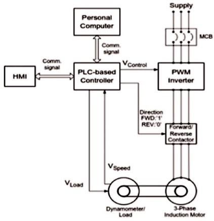
Figure 5. Physical System Layout with HMI, PLC, PWM Inverter, Induction Motor and Load (Saad & Arrofiq, 2012)
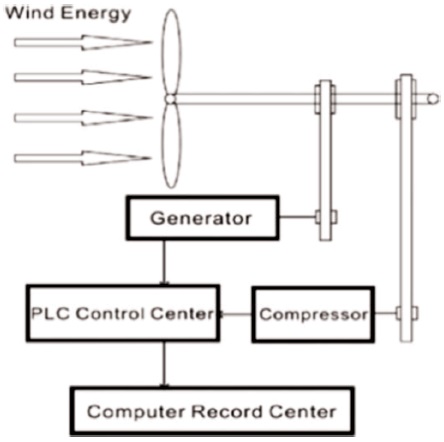
Figure 6. Wind Forced Dual System in Connection with the PLC (Ting et al., 2011)
PLC developed in 1960s, has now become one of the key part of automation systems. From the review that has been presented in this paper, PLC is conformable to any small, medium and high scale applications. Advancement in PLC in the form of size, shape of hardware and user friendly operating software, has become one of the popular and cost effective automation tool.
In coming years, we can see that PLC becomes more suitable tool in commercial and industrial applications because of its diverse architectures, programming languages and types. With SCADA software it can be integrated with many applications.