Figure 1. The Proposed Novel Topology with Regenerative Braking Machanism
Due to overall performance regarding high power density and simple control, Brushless DC (BLDC) motors are broadly used in speed drive applications. The torque of BLDC motors is steady under ideal conditions. With the advent of BLDC motors, high speed automobile industry is booming day by day. Here, a converter topology is proposed for four quadrant operation of BLDC drive. The motion operation is carried out by conventional emf injection method; while the braking operation is conceded by regenerative braking. The present work focuses on multi quadrant operation and tuning the performance of BLDC drive. The simulation studies with regenerative braking mechanisms employing BLDC drive shows better adaptability to the electric hybrid vehicles. The MATLAB SIMULINK simulation results show the performance of the proposed methodology. The corresponding prototype modeling is also presented here with electric hybrid vehicle.
The requirement of high efficiency, compactness, constant torque and high speed made the vast usage of Brushless DC (BLDC), motor in aerospace, military, automotive, industrial, transportation and domestic (Bist & Singh, 2014). The BLDC motor is usually equipped with electronic controller as commutator, i.e., electronic commutator which requires precise control mechanisms. This concept of commutation put the idea of four quadrant operation to BLDC motors before researchers. Hence, the researchers proceed forward in this direction focusing on accuracy, stability, reliability problems with no vibration features at all speed ranges. After the evolution of motors into automobile industry, the BLDC motor of the hub type is widely used in electric hybrid vehicles (EHVs). Today the scenario of high- speed vehicles with BLDC motors is a booming research area towards clean and green transportation (Bist & Singh, 2014).
Further, knowledge on braking operation and its application in EHVs is important. Earlier, the EHVs used mechanical braking for halting purpose. However, from the energy saving point of view, the mechanical brake dissipates much energy. Now this is replaced with electrical braking mechanisms. Later, the known electrical breaking methodologies like dynamic braking, plugging and regenerative braking are applied to the BLDC motor. Thus, both the electric brake and energy regeneration are achieved quite easily. So far, many articles have discussed this kind of energy regeneration and halting procedures in high speed vehicles.
In view of this, the present work focus on electronic commutator with chopper and backing capacitor topology for EHVs driven with BLDC motors. The electronic commutator is a phase controlled converter which either acts as inverter or rectifier depending the requirement. The chopper is mechanized in such a way that, during its ON position the BLDC motor is driven in motoring mode and during its OFF position the BLDC motor is driven in braking mode. The energy backing is done through the capacitor. Two substituent resistors are considered to guide and take away the excess energy or heat decimation if any, in the primary circuit during braking.
The simulation studies at different duty cycles of chopper and braking mechanisms employing BLDC drive shows better adaptability to the EHVs of the present day. The corresponding MATLAB/SIMULINK simulation results are presented here with. The prototype EHV is further developed based upon the simulation results and ratings considered. The experimentation and simulation results comply with each other and are satisfactory. The developed model is presented for perusal.
The proposed topology of BLDC motor for motoring and braking mode of operation is shown Figure 1.
Figure 1. The Proposed Novel Topology with Regenerative Braking Machanism
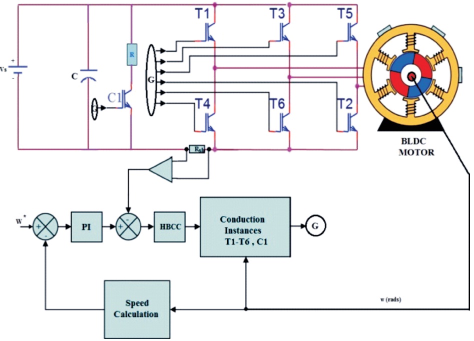
The proposed electronic commutator which is a voltage source converter (VSC) consists of switches 'T1-T6'. This VSC is usually a phase controlled rectifier. It serves as inverter primarily under motoring operation of BLDC motor and secondarily as rectifier during braking operation (Awaze, 2013).
The one other switch C1 is mechanized to work as chopper. This chopper facilitates the power reversal phenomenon with its state (Bist & Singh, 2014). If C1 is said to be ON the BLDC motor is driven in motoring mode and during its OFF position the BLDC motor is driven in braking mode.
The energy balancing is scheduled by capacitor 'C'. The resistors 'R' and 'Rsh' operate along with 'C' during motoring and braking operation to guide the excess energy in the circuitry.
The working of the topology is explained below:
The Vdc is supplied to the proposed topology. Hence the different levels of output voltages obtained are given as, ±1 and 0 which usually represent ±Vdc and 0 upon the sensing phenomenon of Hall sensors. The following hall sensor values and the corresponding switching pattern of the switches are illustrated in Table1.
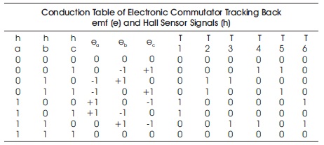
Table 1. Hall Sensor Values-Switching Pattern of the Switches
Particularly for EHVs, along with control over starting one should equally focus on stopping of the EHV. EHVs are usually started with conventional starting methodologies. But, halting the EHVs at desired position is important task in front of researchers and engineers (Awaze, 2013; Vinatha et al., 2008). Hence research towards developing and applying adaptable braking methods for halting the EHVs at desired position is taking a step ahead day by day.
Usually the term braking means halting the motor, i.e., making the speed to zero in less time. The braking is usually termed in two ways, Mechanical Braking and Electrical Braking.
Earlier at low speeds mechanical braking is preferred which halts the motion by the concept of friction applied through mechanical brakes. But these require continuous maintenance and extra cost. With negative torque provision the machine will work as a generator converting the absorbed mechanical energy from load to electrical energy, called as electrical braking. In case of EHVs, prefect halting and energy recovery is carried out by electrical braking.
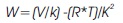
When sensing negative torque braking is applied, both input current and back emf are out of phase. The electromagnetic torque developed by the motor is given as

where T: Torque developed in Nm, Eb: Back emf generated upon loaded condition in volts, Ia : Source current through stator in ampere and Wr : Speed in rad/s.
The forward braking and reverse braking is obtained in second and fourth quadrant. Here, the regenerative braking is preferred over other braking methods because of its advantages. The phenomenon of regenerative braking with the proposed topology is explained below:
Here the concept of regenerative braking, i.e., the power generated during retardation (Eb >Vs) is given back to the source rather wasting it through external resistance, such as insertion and dynamic braking of DC motor. This is later enhanced and expanded to BLDC motor with the proposed topology. The chopper circuit helps in producing negative torque with which the motor runs as generator and hence leads to the operation of regenerative braking. This happens under two conditions (Joice et al., 2011):
Under these two conditions generated power is fed back to the supply.
From the basics of electrical machinery (Joice et al., 2012), to increase the back emf greater than the supply voltage, the speed has to be increased. Like DC motors increasing the field flux exceeding rated value is not possible in BLDC motors because of its trapezoidal flux phenomenon. Therefore, the regenerative braking is applied with fixed voltage source for speeds above rated speed and with variable voltage source for speeds below rated speed (Chu et al., 2004).
Under abnormal conditions like short circuits or open circuits, the chopper circuit and VSC is not sufficient to guide the energy during braking mode. Therefore, two resistors R during motoring operation and Rsh during braking operation is provided in the proposed topology to safeguard the power and logic circuits from the extra generated energy. If not, insulation breakdown will happen with the generated power and damage the entire circuitry.
The speed and torque is mathematically related by the Equation (2):
where W: speed in rad/s, T: Torque developed in Nm, V: Source voltage to BLDC motor or stator supplied voltage in volts, R: motor conductor resistance (rotor) and k: motor constant.
Here, the back emf is made greater than source voltage by just isolating the source voltage from the power circuit. Assuming the power circuit has source voltage 0V then Equation (2) is modified as Equation (3):

The Equation (3) will look like a straight line passing through origin, where R/K2 is the effective slope of the line between speed and torque axis. So, finally the speed torque relation is given as a straight line which passes through origin with R/K2 as slope.
The four quadrant operation of BLDC motor for EHVs is performed in MATLAB/SIMULINK environment. The efficacy of the proposed topology is verified through the simulation and by implementing the prototype for EHV. In this paper, initially the BLDC motor is started as motor and after attaining a steady speed the braking is employed ensuring negative torque. The illustration of proposed topology is as shown in Figure 2. The internal logic conversion mechanism and switching pattern is as shown in Figure 3(a) and Figure 3(b). The corresponding conduction table or switching table is illustrated in Table.1.
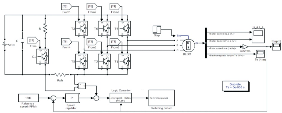
Figure 2. Simulink Diagram Representation of Proposed Converter Topology Fed BLDC Motor
The VSC is given with the switching pattern developed by the logic controller. The VSC is energized through chopper circuit. The chopper, upon its switching instances will operate in bucking and boosting mode. In bucking mode, the chopper along with VSC do the motoring operation either in forward or reverse direction, depending upon ±Vs in quadrants I and III respectively. The duty cycle control of chopper plays a significant role in energy transfer. The performance of chopper for duty cycle ratio of 50% and 75% is illustrated in Figure 4 and Figure 5.
Figure 4 and Figure 5 illustrates the chopper source voltage, output voltage, output current and output voltage average and RMS values at duty cycle of 50% and 75 % during motoring operation.
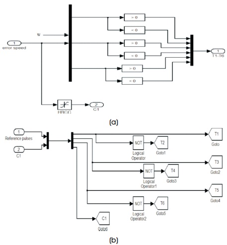
Figure 3. (a) Logic controller and (b) Switching pattern of proposed converter topology fed BLDC motor
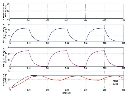
Figure 4. The Performance of Chopper with Duty Cycle 50% Under Motoring Mode
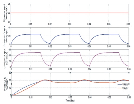
Figure 5. The Performance of Chopper with Duty Cycle 75% Under Motoring Mode
Similarly, in boosting mode, the chopper along with VSC do the braking operation either in forward or reverse direction depending upon energy transfered due to negative torque because of ±Eb in II and IV quadrants respectively. The duty cycle control of chopper along with capacitor C, plays an important role in energy transfer from motor to source. The performance of chopper for duty cycle ratio of 50% and 75% is illustrated here with in Figure 6 and Figure7.
The Figure 6 and Figure7 illustrates the chopper source voltage, output voltage, output current and output voltage average and RMS values at duty cycle of 50% and 75 % during regenerative braking operation.
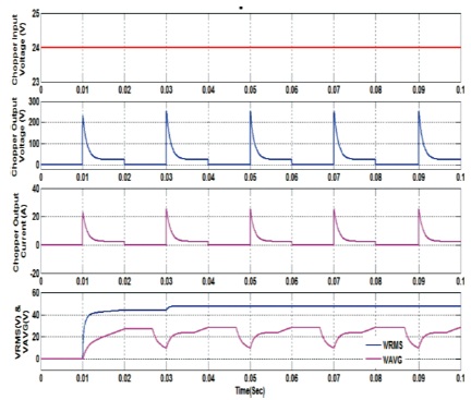
Figure 6. The Performance of Chopper with Duty Cycle 50% Under Braking Mode
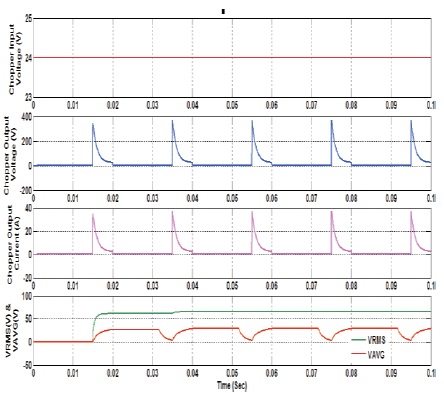
Figure 7. The Performance of Chopper with Duty Cycle 75% Under Braking Mode
However, resistor R during motoring operation and Rsh during braking operation is provided in the proposed topology to transfer and safe guard the power and logic circuits from the extra generated energy.
The phenomenon of regenerative braking is applied after starting the motor and ensuring that they reach the steady state. Now, upon sensing the instant steady state at 0.1s, the regenerative braking is applied at 0.25s and the corresponding simulation results of the braking phenomenon is follows:
Figure 8 illustrates the stator current and back emf of phase A in motoring mode up to 0.25s and regenerative braking mode from 0.25s. The sources current first reduces to zero, following that back emf also traces the source current.
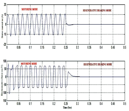
Figure 8. Stator Current and Trapezoidal Back emf of BLDC during Motoring and Regenerative Braking
The Figure 9 (a) illustrates the electromagnetic torque and speed in motoring mode up to 0.25s and regenerative braking mode from 0.25s. The electromagnetic torque is positive up to 0.25s, till motoring operation is performed. At 0.25s, negative torque is sensed and the phenomenon of regenerative braking is applied through chopper circuitry. At this instant of regenerative braking, the BLDC motor running in steady state comes to rest position instantly, which is illustrated in Figure 9 (b).
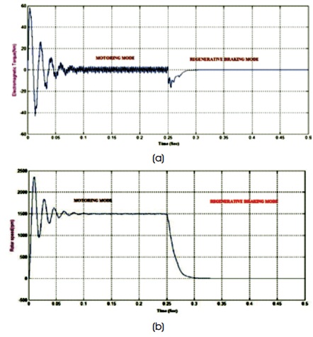
Figure 9. a) Torque and b) Speed Waveforms for Regenerative Braking
The speed torque characteristics of BLDC motor in motoring and regenerative braking conditions under transient and steady state is discussed in Figure 10. The speed inherently depends upon back emf and torque depends upon stator currents to the BLDC motor. At the instant of braking, when supplied voltage to the power circuit is 0 V, the available back emf is the only voltage in the power circuitry which reverses the polarity with same magnitude. Hence, the BLDC motor in I quadrant running at 1500 rpm speed changes the direction because of reversal of power and runs in II quadrant with the same speed. But, upon the charging capacity of capacitor C and stored energy in terms of back emf the motor halts to zero speed in less time. The characteristics is illustrated in Figure 10 with blue color line.
Similarly, with reverse application of supplied voltage to chopper, i.e, -Vdc the quadrants III and IV operation is obtained. In III quadrant reverse motoring is obtained and in IV quadrant reverse braking is obtained. The characteristics is illustrated in Figure 10 with red color line.
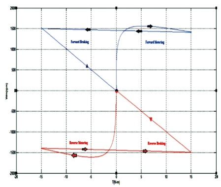
Figure 10. Torque–speed Curve during Regenerative Braking
On obtaining satisfactory simulation results, the prototype of EHV is developed with the specified ratings in Table 2.
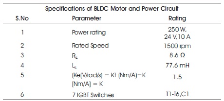
Table 2. Specifications of BLDC Motor and Power Circuit
Logic circuit with IGBT based inverter fed BLDC drive using microcontroller chip is shown in Figure 11. Based on the simulation results, the MATLAB file is converted and embedded into the microcontroller. This control circuit along with power circuit is combined to organize the working of EHV. Here, EHV is a tricycle energized from a small wind generator and two 12 W solar panels are installed to support 250 W, 24 V, 10 A BLDC motor. The solar panels or wind generator charge the two 24 V batteries connected via static transfer switch (STS). This STS guides the power automatically either with wind generator or with the solar energy charged batteries, to meet the required specifications of the BLDC drive.
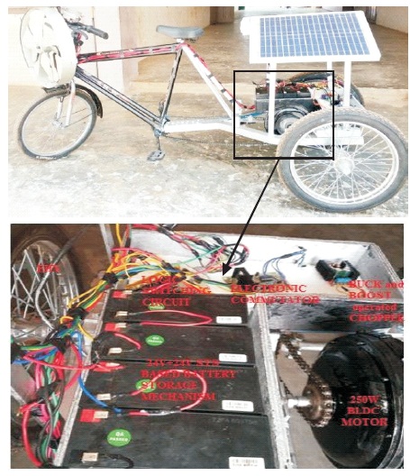
Figure 11. EHV with the Proposed Topological Control and Power Circuits
Initially, BLDC drive of EHV utilizes the charge from batteries and does the accelerating action. Under normal operating conditions, the solar panels can charge the batteries to the required level. But keeping in mind of environmental conditions, a small wind generator is also capable of driving BLDC is incorporated as shown in Figure 11. This wind generator comes into action just after the EHV is into acceleration. The inside view of the power and control circuit is shown in Figure 11.
The front end indicator shown in Figure 12 shows the full charge indication with a meter and light indicator. The EHV designed has a maximum speed range of 50 kmph as indicated in display.
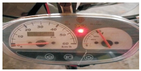
Figure 12. EHV Front End Indicator
This paper proposes a simple control and power circuit topology based EHV employing BLDC drive. The prototype worked with good acceleration and retardation features. The retardation phenomenon is performed by regenerative braking. The energy released during braking is diverted to charge the batteries via power circuitry. Observations from simulation and experimental results show the efficacy of the proposed system.