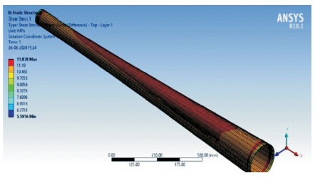
Figure 1. Shear Stress for Carbon Epoxy for Layer 1 Top Side
Substituting composite structures for conventional metallic structures has many advantages because of strength to weight ratio. Laminated composites, with their advantage of higher specific stiffness, gained substantiality in the field of torque carrying structures through many applications. Composite drive shafts has the ability of being the lighter and longer life drive train with higher critical speed. This work aim stop provide an alternative of conventional steel drive shaft for an automotive application and investigates for different combinations of composite materials and different stacking sequence opposite torque directional so determine the natural frequency of composite drive shaft with the help of ANSYS 18.1.
Composite materials could also be outlined as a large combination of two or more materials having a recognizable interface between them. Composite materials usually have a fiber or particle phase that is stiffer and stronger than the continuous phase. Nowday's people are using composite materials for several applications in various fields, a few of them are aerospace, automotive, construction, etc. Safa Ben Arab (Arab et al., 2017) and Charles W. Bert along with Sudharkar Reddy (Bert & Reddy, 1982) studied vibratory behavior of rotating composite shafts. Serge Abrate (Abarate, 1994) did a study on optimum design of laminated plates and shells subjected to constraints on strength, stiffness, buckling loads, and fundamental natural frequencies. Mateen Tariq and team (Tariq et al, 2018) examined the effect of hybrid reinforcement on the performance of filament wound hollow shaft. Krupa Prasad and Aiswarya (Prasad & Aiswarya, 2016) conducted a study on buckling behavior of delaminated plates subjected to in-plane compressive loads. S. Rajendran and Song (Rajendran & Song, 1998) did a modeling using finite element against delamination buckling of composite panels. D. Dinesh and Raju (Dinesh & Raju, 2012) and P. Satheesh Kumar Reddy and Nagaraju (Reddy & Nagaraju, 2017) worked with the replacement of conventional two-piece steel drive shaft and also in minimizing the weight of composite drive shaft. Yefa Hu and team (Ho et al., 2015) studied the torsional capacities of a stacking sequence that vary greatly with torque direction, and established reasonable lay-up design can reduce the difference. Ercan Sevkat and HikmetTumer (Sevkat & Tumer, 2013) stated that residual torsional properties of composite shafts are subjected to impact loadings. A.R. Abu Talib and team of researchers (Talib et al., (2010) found that from the best to the worst stacking sequence, the drive shaft causes a loss of 46.07% in its buckling strength, which represents the major concern over shear strength in drive shaft design. M. A. Badie and researchers (Badie et al., 2006) studied the effect of fibre orientation angles and stacking sequence on the torsional stiffness, natural frequency, buckling strength, fatigue life and failure modes of composite tubes.
Kim et al. (2001) examined composite propeller shafts bonded with aluminium yoke joints and single composite layer joint and found the combination of length, diameter and thickness for 3500 Nm static torsion capacity, whereas Lee et al. (2004) claimed that their designed aluminium composite shaft had 75 % mass reduction and 160 % increase in torque capability. Badie et al. (2006) studied the effect of fibre orientation angles and stacking sequence on the torsional stiffness, natural frequency, buckling strength, fatigue life and failure modes of composite tubes. Mutasher (2009) studied the maximum torsion capacity of the hybrid aluminium/composite shaft for different winding angle, number of layers and stacking sequences. Talib et al. (2010) examined the effect of stacking sequence and fibre orientation moving from the best to worst stacking sequence, the drive shaft causes a loss of 46.07% in its buckling strength.
This paper proposes a comparative study with the base paper Rao et al. (2016) to find out better combination of materials for composite shaft to withstand torsion and to have a longer life. Therefore a drive shaft made of composite material with different materials like carbon fiber, aramid fiber and boron with different stacking sequence will be analysed for torsional rigidity and natural vibration. By applying clockwise torque and counterclockwise torque the influence will be studied under varying loading condition.
The technical data of the composite propeller shaft as given in the base paper (Rao et al., 2016) are as follows:
Length of the shaft: 1730 mm
Mean radius of the shaft: 40 mm
Thickness of the hollow shaft: 4.578 mm (Carbon/epoxy shaft)
Maximum torque applied: 2030 Nm
Ansys 18.1 software is used for the analysis of this study. Shear stress between layers have been plotted in Table 1 and the values are in line with the base paper a few of them have been shown from Figure 1 to 8. Figure 1 shows the validation of shear stress of carbon epoxy for layer 1 top side, all the contour figures have not been shown in the figure; the values are represented in Table 1. Figure 2 shows shear stress for carbon epoxy for layer 4 top side, as composite is made in sandwich system therefore while application of torsion stresses will be induced between the two successive layers is represented in these contours. Figure 3 shows shear stress for carbon epoxy for layer 4 bottom side, Figure 4 shows shear stress for carbon epoxy for layer 6 topside, the maximum value of shear stress has been considered. Figure 5 shows shear stress for carbon epoxy for layer 6 bottom side, the drive shaft is considered as fixed from one end as one end is towards the wheel and it takes a lot of effort to overcome inertia and bring the wheels in motion the other side is connected towards the engine side which delivers the torque; torque is applied as mentioned in the base paper. Figure 6 shows shear stress for carbon epoxy for layer 8 bottom side, Figure 7 shows shear stress for carbon epoxy for layer 10 top side, Figure 8 shows shear stress for carbon epoxy for layer 10 bottom side.
Figure 1. Shear Stress for Carbon Epoxy for Layer 1 Top Side
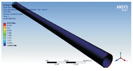
Figure 2. Shear Stress for Carbon Epoxy for Layer 4 Top Side
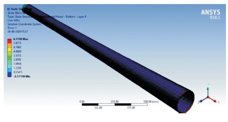
Figure 3. Shear Stress for Carbon Epoxy for Layer 4 Bottom Side
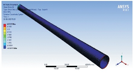
Figure 4. Shear Stress for Carbon Epoxy for Layer 6 Top Side
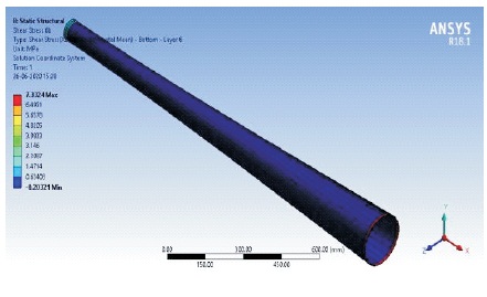
Figure 5. Shear Stress for Carbon Epoxy for Layer 6 Bottom Side
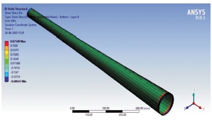
Figure 6. Shear Stress for Carbon Epoxy for Layer 8 Bottom Side
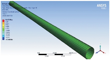
Figure 7. Shear Stress for Carbon Epoxy for Layer 10 Top Side
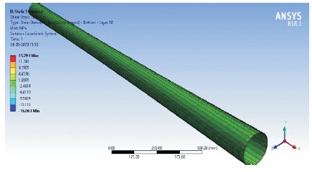
Figure 8. Shear Stress for Carbon Epoxy for Layer 10 Bottom Side
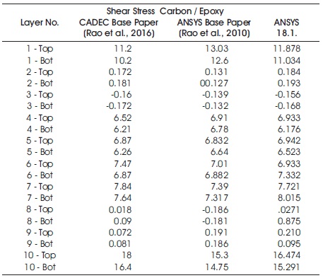
Table 1. Validation of Shear Stress Carbon / Epoxy
In this study carbon/epoxy is altered with boron/epoxy and aramid/epoxy and are compared to determine the better material amongst the three. Table 2 shows the properties of different material obtained from (Reddy & Nagaraju, 2017; Tariq et al., 2018) respectively.
Table 3 indicates that shear stress between two layers are varying and not giving a clear consensus but maximum shear stress and von-Mises stress clearly states that aramid/epoxy is a better material for automotive propeller shaft.
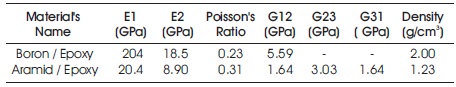
Table 2. Material Properties

Table 3. Comparison of Different Material Composite Shaft
Following the results from section 4.1, aramid/epoxy is considered for comparision with stacking sequence. The stacking schemes are shown in Table 4.
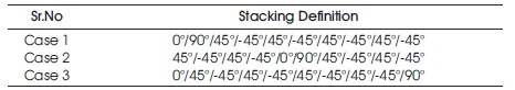
Table 4. Stacking Schemes
Based on different stacking sequence the resultant stress between two layers have changed. The shear stress between the two layers have also changed while between the successive layers for two different cases there is no change. The shear stress in case 1 and case 2 are same. But the maximum shear stress and von Mises stress have no change for all the three cases as shown in Table 5. Layer 1 top, layer 6 bottom and layer 10 bottom have been chosen randomly and have been used for comparison of all the cases. This helps to conclude that stacking sequence plays a vital role in fabrication of composites.
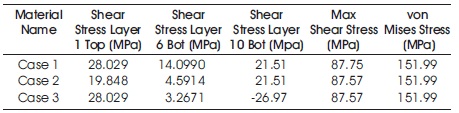
Table 5. Comparison of Different Stacking Sequence
A stacking sequence showing good results may not be able to exhibit the same strength in opposite torque direction of rotation. Thus, clock wise and counter-clock wise rotation are also needed to be examined. The clockwise direction of aramid/epoxy is already examined, Therefore counter clockwise direction analysis contours are needed, and is shown in Table 6.
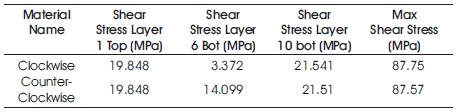
Table 6. Comparison of Clockwise and Counter Clockwise Torque Direction
Many a times it is seen that while changing the direction of the rotation of shaft the same stacking sequence do not play the same role as in automotive propeller shaft forward direction as well as reverse direction both are supposed to be used. Therefore, clockwise and counter clockwise cases are investigated and found that in some layers shear stress is varying.
Free vibration analysis was done to find the fundamental and derived natural frequencies on the composite propeller shaft and its respective mode failure shapes. Boundary conditions are applied by assuming the shaft is pinned-pinned shaft, and no load on the shaft. The frequenties are tabulated in Table 7.
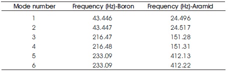
Table 7. Comparison of Natural Frequency
Two different materials (namely boron/epoxy, aramid/epoxy) three different stacking sequences and two different directions of torque rotation (clockwise and counter clockwise) and their natural frequencies are studied using finite element modelling with the help of ANSYS 18.1 work bench. The results obtained may be concluded as: