Figure 1. Safety Layer Matrix
Many industrial facilities, especially those in the chemical, oil & gas and petroleum industries, involve inherent risk in operations due to the processing of material which are hazardous in nature. It is therefore, necessary to precisely identify & analyze the hazards, its operability issues, associated risks and its consequences. Safety instrumented systems (SIS) are often used to reduce the risk associated with process or plant to the acceptable or tolerable level. The reliability of safety function(s) implemented through SIS is determined by the magnitude of risk reduction and is provided in terms of safety integrity level (SIL). The determination of SIL is the method of determining the risk reduction magnitude to safety instrumented function (SIF). There are several techniques used to establish SIL to SIF. These are qualitative, quantitative or mix of both, based on the application under consideration. Layer of protection analysis (LOPA) is one of the prevailing methods to determine the SIL. This paper aims to establish when, why and how to apply the LOPA to determine the safety integrity level (SIL) and finally reached to the conclusion that LOPA is one of the best method for determine the SIL.
SIL assignment is one of important activities in SIS safety life cycle phase. According to IEC 61511-1 allocation of safety functions to the protection layer just start after the hazard and risk calculation completed (ANSI/ISA 84.01- 1996). However there is a case where the safety allocation or SIL assignment activity happen in parallel along-with hazard and risk calculation study. In practice, Layer of protection analysis (LOPA) method is performed for the safety functions with high consequence severity for which in-depth analysis requires. LOPA method begins with data established in the hazard and operability analysis (HAZOP) study and it counts for each recognized hazard by verifying the initiating root cause and the protection layers that prevent or mitigate the hazard. The total amount of risk reduction can then be calculated and the need for more risk reduction is further checked. If added risk reduction is required and if it is to be delivered as a practice of a Safety Instrumented Function (SIF), the LOPA approach allows the finalization of the appropriate Safety Integrity Level (SIL) for the SIF.
SIL assessment starts just after completing the HAZOP, expending the recommendation made during the HAZOP and identified safety functions. IEC 61511-3 (IEC61511, 2003) provides the guidelines on different methods to govern the SIL for safety instrumented functions for specific application. The selection of method for a particular application will depend on many factors which include:
Following is the list of different methods (ICE 61511, 2017) used in process industries for SIL allocation:
ALARP as low as reasonably practicable principle is mainly used to establish the tolerable risk target for the facility under consideration and not used to actually determine the SIL levels. Practically, ALARP is the basic fundamental techniques for the management of risks and used in association with other SIL determination methods like SIL risk matrix (safety layer matrix), calibrated risk graph and layer of protection analysis (LOPA).
In some applications more than one method may be used but in reality client/owner choose the most suitable method for the facility under consideration. IEC 61511 (2017) states that the methods used to allocate the SIL to SIF depend, primarily upon whether the necessary risk reduction is specified explicitly in a numerical manner or in a qualitative manner. These approaches are termed quantitative and qualitative methods respectively.
A qualitative method is used as a first-pass to calculate the required SIL for SIFs. Those safety loops which are allotted a consequence severity level to 3 or 4 by this method should then be further analyzed in more depth using a quantitative method to obtain a more severe understanding of SIL.
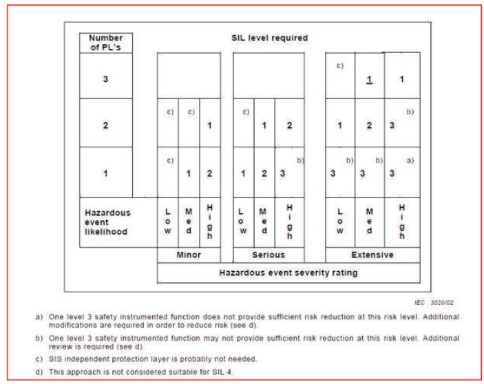
It is a qualitative method for risk evaluation. A risk matrix can be used for the evaluation of risk by combining the likelihood and the impact severity rating of hazardous events. A similar approach can be used to develop a matrix that identifies the potential risk reduction that can be associated with the use of a SIS protection layer. Such a risk matrix is shown in Figure 1.
Figure 1. Safety Layer Matrix
In Figure 1, the safety target level i.e. SIL has been embedded in the matrix. In other words, the matrix is based on the operating experience and risk criteria of the specific company, the design, operating and protection philosophy of the company, and the level of safety that the company has established as its safety target level.
Safety layer matrix is not normally used in the process industry and can be used along-with HAZOP/SIL determination sessions. This method can be used as a screening method which filtered out and to identify the high magnitude safeguards (SIL 2 & 3), which can be further assessed in separate risk evaluation sessions.
This is a qualitative method to determine the safety integrity level of a safety instrumented function from a knowledge and understanding of the risk factors associated with the process and basic process control system. The risk graph is based on the principle that risk is proportional to the consequence and frequency of the hazardous event. It begins by assuming that there is no safety instrumented systems exist, although typical non safety systems like BPCS and monitoring systems are in place. Consequences are related to harm associated with people, equipment and environmental damage.
This method shall consider the following four risk parameters:
By combining the above mentioned four risk parameters, a risk graph can be formed which in turn results in embedded SIL numbers. This risk graph shall be separate for people, assets and environment risk and the most conservative SIL number is used as overall SIL of the SIF under consideration. An example risk graph is given in Figure 2.
The general scheme of the risk graph is given in Figure 3.
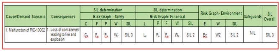
Figure 2. Risk Graph Example
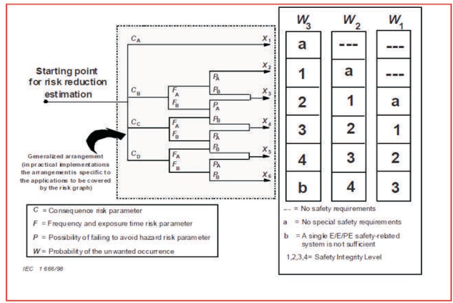
Figure 3. Rick Graph General Scheme
This is a semi-qualitative method that enables the safety integrity level of a safety instrumented function to be determined from a knowledge of the risk factors associated with the process and basic process control system. Calibration of the risk graph is the process of assigning numerical values to risk graph parameters. This forms the basis for the assessment of the process risk that exists and allows determination of the required integrity of the safety instrumented function under consideration. Find below the sequence steps involved in methodology to determine the SIL.
Fault tree and event tree (Figures 4 and 5) are semi- quantitative and quantitative methods. It is used to evaluate the process risk by determining the frequencies of hazardous events. These frequencies are then used to compare with the pre-defined tolerable frequency. Any inadequacy is expressed in terms if SIL and this SIL value are normally assigned to develop a new SIF. Both of these methods can be used independently however if used in combination may become more powerful and rigorous method for determining SIL. Fault tree and event tree analysis often requires the use of specialized, quantitative risk assessment software. The main disadvantage of this method is that requires skill in probabilistic modelling to apply properly.
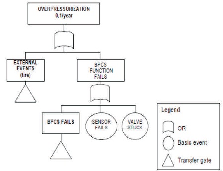
Figure 4. Fault Tree
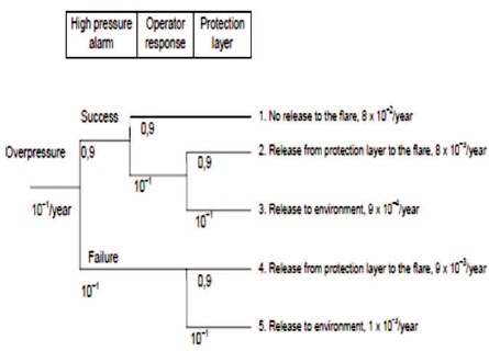
Figure 5. Event Tree
Layer of protection analysis is a simplified but more detailed semi-quantitative risk assessment method. The LOPA method was established by the American Institute of Chemical Engineers (AIChE) in 1993. The method begins with data established in the HAZOP study and calculates for each identified hazard by documenting the initiating cause and the protection layers that prevent or mitigate the hazard. The total amount of risk reduction can then be determined and the need for additional risk reduction analyzed. If supplementary risk reduction is required and if it is to be provided in the form of a Safety Instrumented Function (SIF), the LOPA methodology allows the determination of the appropriate Safety Integrity Level (SIL) for the SIF (Risktec, 2010).
LOPA can be used during any stage of SIL allocation process of the safety life cycle of a plant or the facility under consideration. Being a semi-quantitative method, it is being used more rigorously after the initial qualitative SIL assessment completed. LOPA is normally executed once the qualitative hazard analysis has been completed, which delivers the LOPA team with a list of all hazard scenarios with its associated consequence, its description and its potential safeguards for consideration (Bridges, 2001).
There are few reasons why a more rigorous analysis tool like LOPA may be needed. Following are the list of such scenarios:-
LOPA requires some specific set of supporting documents while risk assessment. Following is the minimum required list of supporting documents generally used in LOPA.
The detailed information needed for the LOPA is enclosed in the data collected and developed in the Hazard and Operability analysis is shown in Figure 6 (HAZOP study), (IEC 61511, 2003; IEC 61508, 2010).
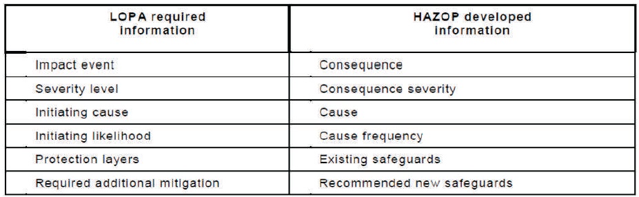
Figure 6. LOPA and HAZOP Terminology
Find below the sequence steps of the methodology to determine the SIL using LOPA.
Step – 1 Impact event
Each impact event description (consequence) as determined from the HAZOP study is entered in column 1 of Figure 7 (typical spreadsheet used for the LOPA).
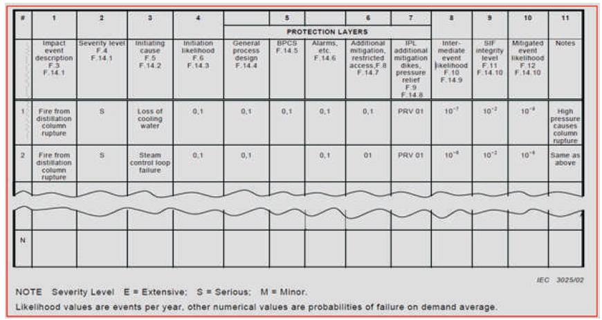
Figure 7. LOPA Worksheet
Step – 2 Severity level
Consequence severity or the severity levels like Minor (M), Serious (S), or Extensive (E) are next selected for the impact event according to Figure 8 and entered into column 2 of LOPA worksheet.
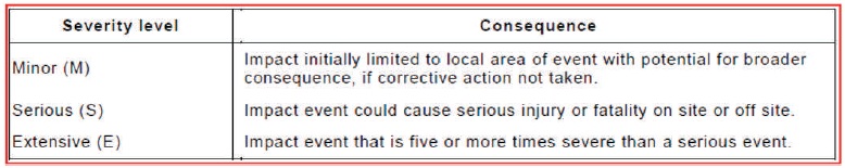
Figure 8. Severity Level
Step – 3 Initiating cause
All applicable initiating causes of the impact event are listed in column 3. Impact events may have many Initiating causes, and it is important to list all of them.
Step – 4 Initiation likelihood
In column no. 4, likelihood values of the initiating causes occurring, in number of events per year, are entered. Figure 9 shows typical initiating cause likelihood. The experience of the team is very important in determining the frequency of initiating cause.
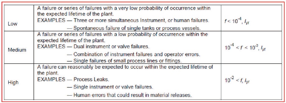
Figure 9. Initiating Event Likelihood
Step – 5 Protection layers
The next fields in the LOPA worksheet are the protection layers is shown in Figure 10. All applicable protection layers with their PFD (Probability of Failure on Demand) average values are identified and recorded in column no. 5, 6 & 7 of LOPA worksheet. LOPA team needs to be very careful while selecting the appropriate protection layers. Because the protection layers that perform their function with a high degree of reliability may only qualify as Independent Protection Layers (IPL) (Thomas, 2011).
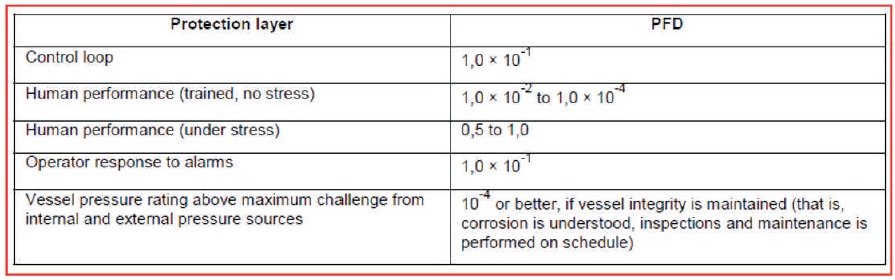
Figure 10. Protection Layer and its Credit
LOPA team should determine the appropriate PFDs for all mitigation layers and list them in LOPA worksheet column. This includes mechanical, structural or procedural and the example would be Pressure relief devices, dikes, restricted access.
Some mitigation layers may reduce the severity of the impact event but not prevent it from occurring. Example would be deluge systems for fire or fume release, fume alarms and evacuation procedures.
Find below the brief criteria to qualify the protection layer as IPL are:
Specificity: An IPL shall be designed to prevent or to mitigate the impact of consequences to one potentially hazardous event (for example, release of toxic material, a loss of containment, or a fire). There may be the possibility that multiple causes may happen which may lead to the same hazardous event; and, therefore, multiple event scenarios may execute action of one IPL.
Independence: An IPL shall be independent than any other protection layers associated with the consequence.
Dependability: An IPL shall be totally dependent and should do what was intended to do with it. Both random and systematic failure modes shall be identified and addressed in the design.
Auditability: An IPL shall be auditable i.e., it shall be designed to assist regular authentication of the protective functions. Full proof testing, partial proof testing and maintenance of the safety function shall be done according to the specification.
Step – 6 Intermediate event likelihood
The Intermediate event likelihood is calculated by multiplying the initiating likelihood (column 4) by the PFDs of the protection layers and mitigating layers (columns 5, 6 and7). The calculated number is in units of events per year and is entered into column 8.
Here the important point to be considered is that “If the intermediate event likelihood calculated in Step-6 is less than the corporate criteria for events of this severity level, additional PLs are not required. Further risk reduction should, however, be applied if it is economically appropriate”.
And the additional mitigation is required, If the intermediate event likelihood is greater than the corporate criteria for events of this severity level. It is important to check the Inherent safer methods and solutions before additional protection layers shall be applied in the form of safety instrumented function (SIF). And if this inherent safe design change is made, then the calculation must be re-run to check if the intermediate event likelihood is below corporate criteria. If the calculation checked as mentioned above and if it fails to reduce the intermediate likelihood below corporate risk criteria, a SIF is required.
Step – 7 Safety Integrity level
If a new SIF is required, the required safety integrity can be calculated by dividing the corporate criteria for this severity level of event by the intermediate event likelihood. A PFD of the SIF below this number is selected avg as a maximum for the SIF and entered into column 9.
Step – 8 Mitigated event likelihood
To calculate the mitigated event likelihood by multiplying columns 8 and 9 and the result is entered in column 10. This is continued until the team has calculated mitigated event likelihood for each impact event that can be identified.
Step – 9 Total risk
The final step is to calculate the SIL number by adding all the mitigated event likelihood of step-7 and step-8.
For example, the mitigated event likelihood for all serious and extensive events that cause fire would be added and used in formulas like the following:
riskoffatalityduetofire=(mitigatedeventlikelihoodo fallflammablematerialrelease)X(probabilityofignition )X(probabilityofapersoninthearea)X(probabilityoffata linjuryin the fire).
It is very much important to properly apply the conditional modifier like time at risk and occupancy factor to be used in the formula to derive the total risk. This requires the expertise of the risk analyst specialist, the knowledge of the team and the work practices followed of the plant and affected community.
If the total risk (results from the criteria as explained above) meets or is less than the corporate risk criteria for the population affected, the LOPA is complete. However, since the affected population may be subject to risks from other existing units or new projects, it is wise to provide additional mitigation and risk reduction if it can be accomplished economically.
3.5 Benefits of LOPA
LOPA is a systematic methodology for examining defense in-depth and assigning the SIL target which has many advantages that justify investment by organizations. Some general benefits of LOPA include (Bridges, 2001).
As explained above, LOPA has many important advantages to be considered as good SIL assignment methodology; however still it has some drawbacks or limitations (Bridges, 2001).
Any SIL selection method, if not used properly may lead to inappropriate SIL target with potentially intolerable level of risk.
Qualitative methods are simple and easy to use; less time consuming and can be used in early stage of project to screen a large number of SIFs. However, it tends to be more conservative and may result in higher SIL requirement (which eventually leads to higher costs).
Semi-quantitative methods are more quantitative in nature and thus more precise than qualitative methods. It can be used during detail engineering stage of the project; or when it is required to validate/review previous results from qualitative/semi-qualitative methods. However, it's more time consuming and requires more resources than qualitative method.
Fully quantitative method — QRA (Quantitative Risk Assessment) is the most resource intensive method. But this is not commonly used in the process industries but still has been used to analyze cases where the risk is extremely high. The FTA (Fault Tree Analysis) or ETA (Event Tree Analysis) methodologies are used to evaluate the scenarios in detail and provide more exact results, for example minimum value of risk reduction factor (RRF) that is required for safety instrumented function. These techniques may be recommended for critical safety functions or when we would like to define exact values of risk reduction or PFD avg target for the SIF.
LOPA allows the SIL allocation team to take a predefined scenario and estimate the risk of the scenario in a consistent and simplified manner. Since LOPA being semi-quantitative method which uses numbers, the final results express the precise risk reduction required of the scenario. The more rigorous procedure of LOPA frequently clarifies inaccurate scenarios result from qualitative hazard reviews.