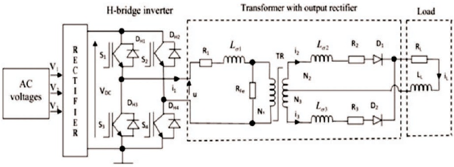
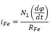
Figure 1. Dynamic Model of RSWS
This paper is an attempt to accomplish a performance analysis of the different control techniques on current spike reduction by means of magnetization level control in the primary winding on the medium frequency transformer based DC spot welding system. Current Spike reduction is an important factor to be considered while spot welding systems are concerned. The current control technique is a piecewise linear control technique that is inspired from the DC-DC converter control algorithms to register a novel current spike reduction method in the MFDC spot welding applications. The different controllers that were used for the current spike reduction by means of magnetization level control of the overall applications involve the hysteresis controller, Proportional Integral (PI) controller. Care is taken such that the current control technique would maintain a reduced current spike in the primary current of the transformer while it reduces the Total Harmonic Distortion. In this research, intelligent control system is introduced by using Adaptive Neuro Fuzzy Inference System (ANFIS). The performance of ANFIS controller is presented considering the parameters, percentage of current spike reduction, and THD. It is proved that current spikes are controlled successfully and has less THD than the above mentioned conventional controllers. Matlab/SimulinkTM based simulation is carried out for the MFDC with 220 KVA welding transformer in resistance spot welding systems.
Resistance spot welding is mostly used in automotive industries and it is very inexpensive and good in efficient material joining processes. The RSW process utilizes currents in the range of 1-200 kA with durations ranging from a few cycles to one second to generate Joule heating. RSW transformers operate within a middle-frequency range of around 1 kHz. Normally, an RSWS consists of an input rectifier, Welding Transformer (WT), and DC/DC converter. The input rectifier transforms the three-phase Alternating Current (AC) input voltages into smooth DC voltage available on the DC-bus. The DC/DC converter transforms the DC-bus voltage into the DC voltage proportional to the DC welding current. For the welding of car body parts, welding currents between 10 kA and 20 kA are required (Takasaki & Sonoda, 2005; Sabate, Vlatkovic, Ridley, Lee, & Cho, 1990). The AC or DC welding currents generated with different types of converters can be used in the spot welding applications (Morimoto, Doi, Manabe, Ahmed, Lee, & Nakaoka, 2005a; Morimoto, Doi, Manabe, Ahmed, & Lee, 2005b).
Due to the variation in the resistance of the secondary winding of the MFDC, RSWS transformer would increase DC component in the primary current of the transformer thus introducing current spike in the primary current of the transformer (Jeon & Cho, 2001). An Artificial Neural Network (ANN) based implementation of the magnetization level detection in MFDC RSWS is introduced in (Klopcic, Stumberger, & Dolinar, 2007). The literature (Klopcic et al., 2007) discusses about the detection of the magnetization level by means of sensing and analyzing the primary winding current of the MFDC transformer. The choice of MFDC spot welding systems comes from the idea that if MFDC is powered from a three phase supply it would consume the current equally from all the phases thus reducing the chances of introduction of harmonic current. The occurrence of the current spike is unavoidable in any spot welding systems, but MFDC has a history of producing lesser current spike. The dynamic characteristics of the spot welding machine is extracted by detecting the current and voltage from the welding systems in order to provide a higher performance welding machines with completely optimized parameters for better working of the welding machines (Stumberger, Dezelak, Klopcic, & Dolinar, 2012). Appropriate A/D converter and the D/A converters are cast-off for the implementation of the automated welding machines (Stumberger, Dezelak, Klopcic, & Dolinar, 2012). Power electronics technology (Saleem, 2012) has been used in resistance spot welding system, where there is a problem of shortest possible rise time and long settling time. In this paper, intelligent control system is introduced and it is proved that it is superior compared with existing control system for RSWS.
The objective of this paper is to design the artificial intelligence based controller for resistance spot welding system in automobile industry. The problems in the conventional control system are sensitive to the vibrations and temperature, not effective in performance in terms of reducing the spikes, less THD, less rise time and settling time. All these factors are making the industrialists are not satisfactory. In the proposed ANFIS based control system, all the above-mentioned drawbacks can be overcome, but in this paper, the focus is on spikes reduction in primary current, less ripple current in welding current of a transformer, and less THD. Superior performance of ANFIS based controller proved numerically as well as simulation side. This can be extended to implement the product in hardware in order to make the resistance spot welding system effective and also satisfy the industrialists.
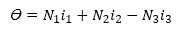
The MFDC RSWS shown in Figure 1 consists of an input rectifier, an H-bridge inverter, a single-phase transformer, and a full wave output rectifier. The three phase alternating voltages V1, V2, V3 supplied from the common electric grid are rectified in the input rectifier in order to generate the direct current bus voltage. The bus voltage is used in the H-bridge inverter, where numerous switching patterns and control strategies can be applied, to generate AC voltage uH, required for supply of the welding transformer. The welding transformer has one primary and two secondary windings. The welding transformer welding current and number of turns in the windings and resistance and inductances respectively can be denoted by i1, i2, i3, N1, N2, N3, R1, R2, R3 and Lσ1, Lσ2, Lσ3. The output rectifier diodes D1 and D2 are connected to both transformer secondary coils.
Figure 1. Dynamic Model of RSWS
The dynamic model of the RSWS was constructed based on the schematic presentation. In this work, the model is built with the programme Matlab/Simulink based on the following set of equations (1)-(9).


The result of simulations, obtained by the dynamic model of the RSWS, shows that small difference in resistances R2, R3 and in characteristics of the rectifier diodes D1 and D2 can cause unbalanced time behavior of the current spikes in the primary currents i1.
With the appropriate dynamic model, the two behaviors of RSWS, the symmetrical and asymmetrical, could be simulated. Firstly, the symmetrical (resistances R2 and R3 are equal) behavior is considered by parameters shown in Table 1, while obtained results are shown in Figure 2(a) in the scale of t= 0 to 0.1 s and expanded result shown in the scale of 0.03 to 0.04 s in Figure 2(b).
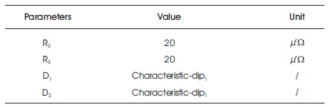
Table 1. Parameters for Symmetrical Behavior of the Resistance Spot Welding System
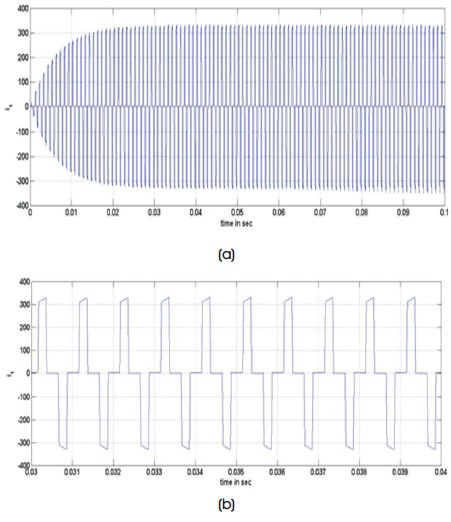
Figure 2. (a) Symmetrical Behavior of Behavior of Resistance Spot Welding System (b) Symmetrical Behavior of Behavior of Resistance Spot Welding System for a Scale of 0.03 to 0.04
Different resistances R2 and R3 and different characteristics of the output rectifier diodes D1 and D2 could cause undesired asymmetry of the spot welding system by considering values shown in Table 2. While simulating, asymmetrical behavior of the resistance spot welding system is clearly seen which is shown in Figure 3(a) in the scale of 0 to 0.1 s and expanded response can also be shown in Figure 3(b).
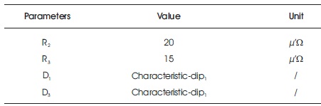
Table 2. Parameters for Asymmetrical Behavior of the Resistance Spot Welding System
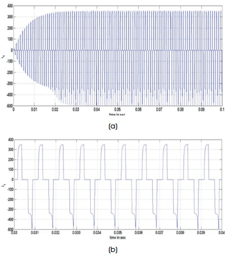
Figure 3. (a) Asymmetrical Behavior of Resistance Spot Welding System (b) Asymmetrical Behavior of Behavior of Resistance Spot Welding System for a Scale of 0.03 to 0.04 s
Symmetrical and asymmetrical behavior of the resistance spot welding system will determine the quality of the welding. For making RSWS smooth operation, spikes due to asymmetrical behavior of resistance and diodes need to be detected and controlled. Major focus in this paper is to design the controller by using intelligent computing technique once spikes are detected. Design aspects of controller is discussed in the following section.
A current controlled strategy is developed by adopting the concept of ANFIS in order to reduce the current spike occurring in the transformer primary current.
The Adaptive Neuro Fuzzy Inference System (ANFIS) effectively controls the state of the welding transformer. The ANFIS technique, in turn, consists of a hybrid system of fuzzy logic and neural network method. The fuzzy logic takes care of the constraints of the system such as the inaccuracy and ambiguity at the time of configuration of the system while the neural network offers it with a sense of flexibility. In the ANFIS system the data is received at the inputs and moved through the system, layer by layer, till it reaches the output. The only input to the ANFIS is represented by the w(t). To reflect different adaptive capabilities, circle and square nodes are used in an adaptive network. In this regard, a square node and the circle nodes are labeled as the adaptive node and fixed node correspondingly.
The block diagram (Figure 4) explains how the implementation is carried out for the proposed current controlled technique in order to control the spike in the transformer's primary current. The i2 and i3 current thus observed from the mathematical representation of the saturation transformer is added and the sum of both the currents that is the magnetizing current is given to the comparator that has reference current as the another input. The error current which is given to the PI controller produces modulation index in such a way that the magnetizing current equals the reference current. By the use of the modulation index the triangular PWM is generated to be fed to the inverter, thus controlling the spike not to cross the desired current.
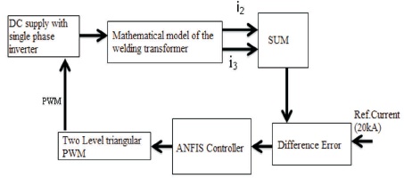
Figure 4. Block Diagram of the ANFIS Controller
The learning algorithm adapts the membership functions of a Fuzzy Inference System by means of the training input-output data. Here, the input-output data represents the “coordinates-angles” dataset. The coordinates function as input to the ANFIS and the angles represent the output. The simplification skill is stepped up only if the ANFIS system is home to an appropriate number of rules. The ANFIS system has found itself extensively employed so as to effectively manage certain machining procedures, which are generally used in the time-tested control procedures. With the intention of realizing a preferred input-output mapping, these constraints are revised in accordance with a specified training data and a gradient-based learning process (Antonelli & Astanin, 2015). In the replication process, the ANFIS design is utilized to give shape to a non-linear function, and locate nonlinear modules in a management mechanism. The gradient technique and the least squares evaluation are integrated to refresh the constraints in an adaptive system. Each and every epoch of the hybrid learning process is home to a forward pass and a backward pass. The forward pass is entrusted with function of propagating the input vector through the network layer by layer. In the backward pass, the error is sent back through the system in an identical method to back propagation.
The algorithm flowchart for ANFIS controller is shown in Figure 5.
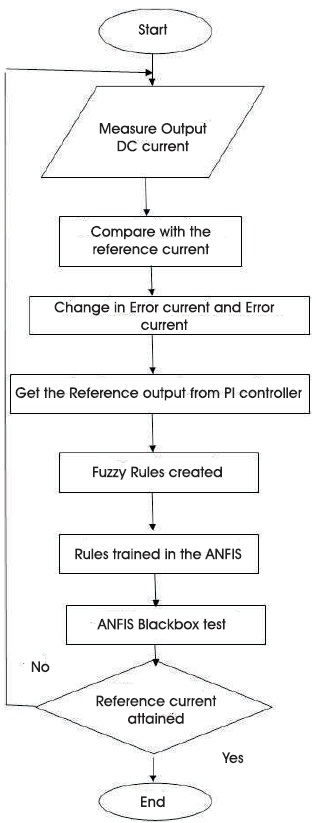
Figure 5. ANFIS Controller Flowchart
Simulation is carried out for 160 KW spot welding system. Only input for the ANFIS controller is welding current and it is set as 20 kA ± 10% variation in welding current, which will be accepted. During the welding process, variations in welding current will occur. Input for this intelligent control system is welding current. When the load current (welding current) reaches the maximum, there will be asymmetry in the system, which leads the core to be saturated and subsequently spikes in primary current of a welding transformer. For controlling these spikes, ANFIS has been designed and controlled spikes are shown in Figures 6 and 7.
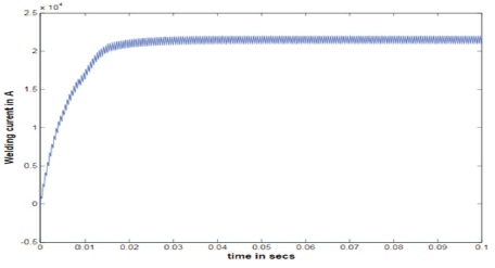
Figure 6. Welding Current of RSWS
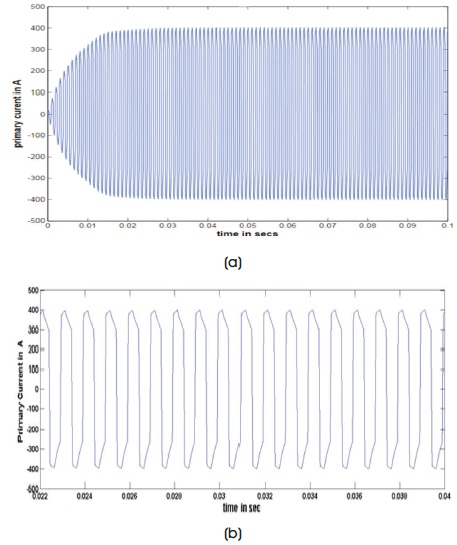
Figure 7. (a) Output of ANFIS Controller (b) Output of ANFIS Controller for a Scale of 0.02 to 0.04 s
Spikes in the primary current and ripple in the welding current can be calculated as under.
Percentage Ripple in welding current,
Percentage Spike in Primary Current,
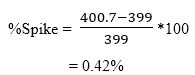
From the above equations, the current spikes are of 0.42% and ripples in welding current are of 2.8%. these spikes in primary current and ripples in welding current are reduced significantly compared with conventional control systems (Subbanna & Suryakalavathi, 2016) and from Figure 7(a), it is clearly seen that almost no spikes are present and magnitude of primary current is within the pre set limit of 400 amperes. THD is 35.89% and is shown in Figure 8. THD is less compared with conventional controllers like Hysteresis and PI controllers (Klopcic, Dolinar, & Stumberger, 2008; Chae, Gho, Mok, Choe, & Shin, 1999) adaptive neuro fuzzy inference system controlled expanded output has been shown Figure 7(b).
Figure 7. (a) Output of ANFIS Controller (b) Output of ANFIS Controller for a Scale of 0.02 to 0.04 s
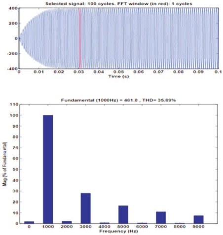
Figure 8. THD of ANFIS Controller
The proposed ANFIS controller is implemented using software package Matlab/Simulink and the results were observed and shown. The superior performance of the proposed ANFIS were confirmed by numerical and simulation results. The ANFIS provides many advantages, in comparison to the classical control of the spot welding system, such as controlling the spikes effectively, less THD, shortest possible rise time, and also less ripple content in the input. Overall performance of the ANFIS based control was seen to be better than the conventional controllers for core saturation level control. In the opinion of the authors, spot welding systems are a very suitable solution for use in automobile industry. This can be implemented in hardware to bring to practice in industries.