Figure 1. Block Diagram of Cuk Converter (Analysis of Four DC-DC Converters in Equilibrium, 2015)
In this paper, a multi input Cuk converter is designed and simulated using a fuzzy logic controller. Multi input Cuk converter have their own applications in DC grid system that can be used to integrate multiple sources together and then create a common DC bus bar. Conventionally, a separate DC-DC converter is required to produce output of each source. This creates a complex network and is also not a cost effective solution. Therefore, a combined converter model is created and simulated in MATLAB using intelligent fuzzy logic controller approach. This helps in minimization of ripple content, power quality improvement, flexibility, and it is efficient in regulation of DC bus voltage. A single stage Cuk converter is designed first using Pulse Width Modulation (PWM) as the control of duty cycle and later using PI controller. The waveform response in both conditions were noted down and analysis were done. Then a fuzzy logic controller for single source is implemented with intelligent algorithm. Improvement in signal quality was noted down with the use of fuzzy logic and later it was incorporated in creating a multi input Cuk converter. Only DC input integration of multiple energy either renewable or non-renewable sources is discussed in this paper.
In the present era of energy crisis, harvesting renewable energy sources is considered to be the most effective alternate source of energy (Liserre et al., 2010; Nehrir et al., 2011). But since these energy are intermittent and stochastic in nature, the problem lies in using them efficiently. Let's take an example of solar energy, here the sources would produce variable energy depending upon weather condition (Rosli et al., 2014). So efficient regulation of DC bus voltage becomes our concern as later DC power is converted to AC power for application. So the primary area of research lies in using standard 12 V DC as input for Cuk converter and then constructing a Multi-input Converter (MIC). These controllers were also proved to be efficient in controlling flow of power from sources to grid (Jiang & Fahimi, 2011). Ripple minimization is also the core area of research for all the three PWM, PI, and Fuzzy logic control strategy. The Cuk converter is simulated for a definite simulation time in Matlab for all the three cases.
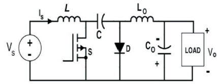
In this stage, a Cuk converter is designed and simulated in Matlab. Figure 1 shows the block diagram of single stage Cuk converter.
Figure 1. Block Diagram of Cuk Converter (Analysis of Four DC-DC Converters in Equilibrium, 2015)
A Cuk converter provides the output voltage that may be less or greater than the input voltage. It is composed of both buck and boost converter topology and the control of duty cycle determines the mode of operation in Cuk converter (Analysis of Four DC-DC Converters in Equilibrium, 2015).
Pulse Width Modulation (PWM) control is a strategy used to encode a message into a pulsing signal (Bimal, 2001). Here, the duty cycle and switching frequency is adjusted to control the required parameter like power and voltage.
A PI control is a feedback control loop that calculates an error signal by taking a difference in output of a system, which is the power being drawn by DC input voltage and the set point. It helps in reducing steady state error and hence improves accuracy of the system (Bimal, 2001). In this research, the use of PI controller eliminated forced oscillation. Here the proportional value (P) is taken as 0.01, Integral (I) as 1, and the sampling frequency as 20 KHz.
A fuzzy logic controller works on basic set of rules, which is defined in the rule and database of the system. It has relaxed boundaries and is dependent on membership function (Brubaker, 1992). In this paper, Mamdani method of fuzzy inference system is deployed and set of rules is created to control the duty cycle of single stage and multi stage Cuk converter.
Figure 2 shows the simulated circuit of single stage Cuk converter. The selected converter was operated with 20% duty cycle and 70% in buck and boost modes respectively and load voltages and input voltages were plotted for both buck and boost mode of operation. Figure 3(a) shows the simulated waveform of load and input voltage (12 V DC) during boost mode.
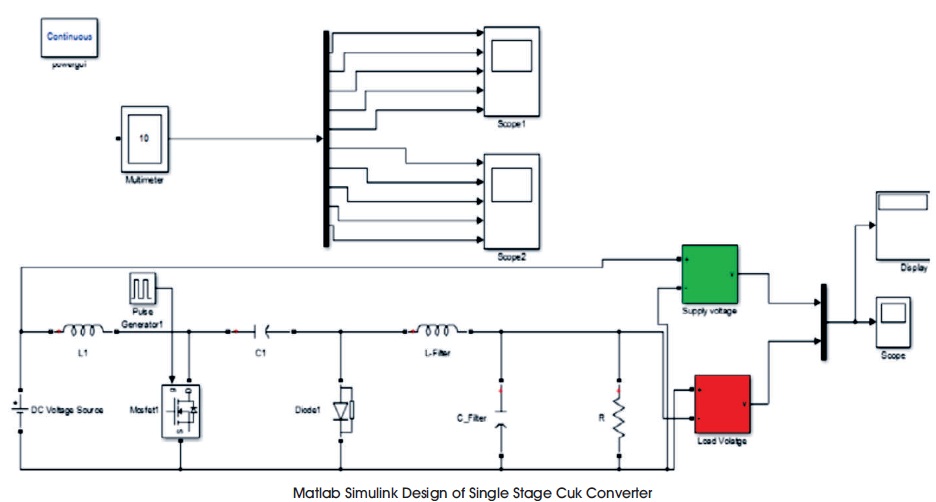
Figure 2. Matlab Simulink Diagram of Single Stage Cuk Converter (PWM Method)
As we can see the output voltage oscillated from initial point to some other voltage and creating a ripple of roughly around 1.76% and finally it settles down to 2.1.9 V represent highly stable and efficient converter system. Figure 3(b) shows the simulated waveform of load and input voltage (12 V DC) during buck mode. Here, the ripple content was noted around 1.69% with settled value of 10.9 V that very much adheres the principle of buck operation.
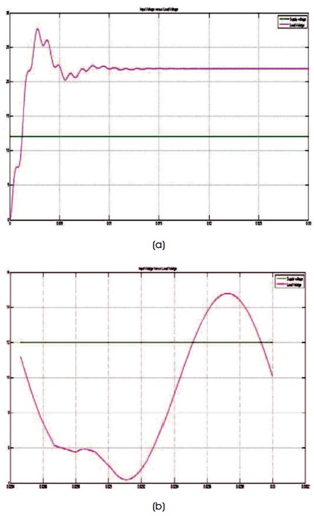
Figure 3. (a) Load Voltage versus Input Voltage during Boost Mode (70% Duty Cycle), (b) Load Voltage versus Input Voltage during Buck Mode (20% Duty Cycle)
The voltage and current across other components of Cuk converter in Boost mode is shown in Figure 4.
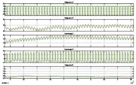
Figure 4. Voltages and Current as of Scope 1
Figure 5 shows a simulated design of same single stage cuk converter with PI control strategy.
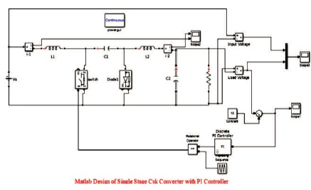
Figure 5. Matlab Simulink Design of Cuk Converter with PI Controller
The load voltage waveform during buck and boost mode are shown in Figures 6(a) and (b), respectively.
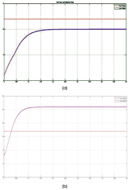
Figure 6. (a) Input versus Load Voltage during Buck Mode (PI Controller), (b) Input versus Load Voltage during Boost Mode (PI Controller)
After simulation, it was observed that the ripple content of Cuk converter when used with PI controller was reduced compared to the conventional PWM control method as the steady state error was reduced. However, the response time was lagging that made the need to look for some other intelligent control methods like fuzzy control method.
Table 1 shows the thorough analysis of the waveform in time domain of Buck and Boost mode.
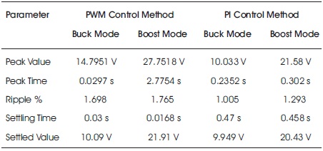
Table 1. Time Domain Specification of Cuk Converter Waveform (PWM & PI Controller)
For fuzzy logic controller, error in voltage, and change of error in voltage were selected as the inputs and duty cycle was selected as the output command of the controller. The system was modeled using the MATLAB fuzzy system tool box.
Figure 7 shows a simulated design of same single stage Cuk converter with fuzzy logic control strategy. The load voltage waveform and pulse waveform during buck mode are shown in Figures 8(a) and (b), respectively.
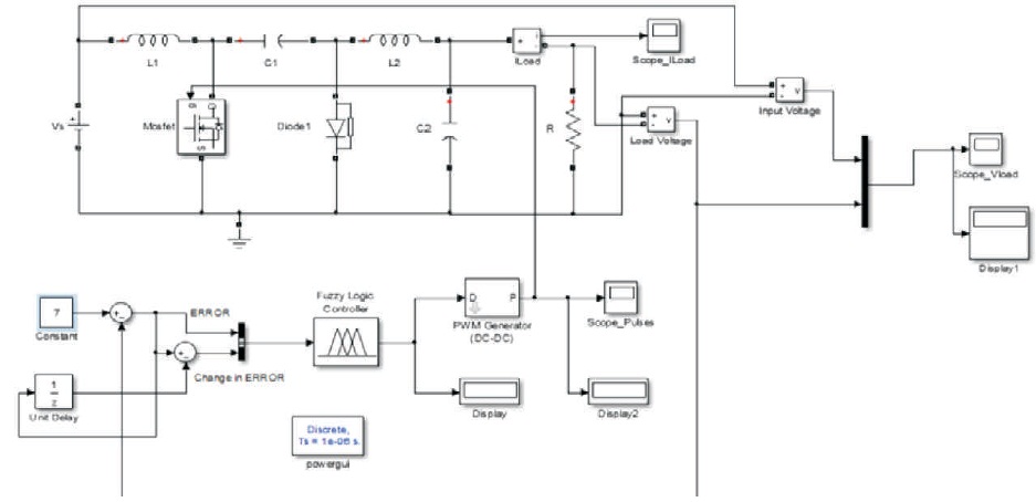
Figure 7. Matlab Simulink Fuzzy System Model for Cuk Converter
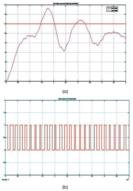
Figure 8. (a) Input versus Load voltage during Buck Mode (Fuzzy Controller), (b) Pulse Waveform in Buck Mode (Fuzzy Controller)
The load voltage waveform and pulse waveform during boost mode are shown in Figures 9(a) and (b), respectively.
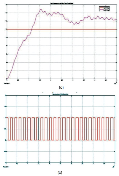
Figure 9. (a) Input versus Load Voltage during Boost Mode (Fuzzy Controller), (b) Pulse Waveform in Boost Mode (Fuzzy Controller)
Figure 10 shows the simulated circuit involving three stage multi-input Cuk converter using fuzzy logic. Here, the fuzzy controller evaluates two inputs which is error and change in error of the voltage and the output which is duty cycle. Set of rules matrix were made into FIS editor of Fuzzy system Matlab toolbox. Mamdani method of fuzzification was employed and centrioid implication for deffuzification was adopted.
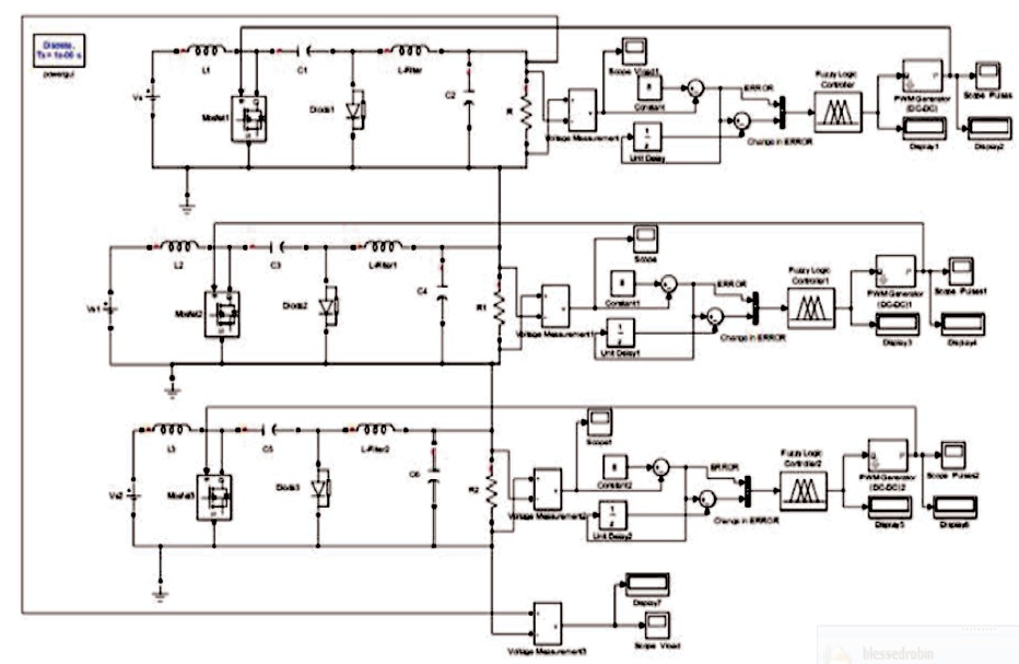
Figure 10. Three Stage Multi-input Cuk Converter based on Fuzzy Controller
Table 2 shows the thorough analysis of the waveform in time domain of Buck and Boost mode.
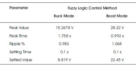
Table 2. Time Domain Specification of Cuk Converter Waveform (Fuzzy Controller)
The above analysis shows the improvement in the response of the system both in buck and boost mode when compared to the conventional PWM and PI control method. Fuzzy logic control is based on learning examples and rules, hence it adjusted the speed of the response intelligently and fired certain set of rules to achieve the convergance to the desired value. Thus, fuzzy logic controller based Cuk converter performed efficiently as compared to other controlling methods.
For multiple input source, a Multi-input Cuk (MIC) converter was designed. There are various topologies of multi-input converter, like buck based, boost based, Cuk based, Sepic based, quad active, flyback based converter (Chen & Yuan-Chuan, 2001). Out of these all, the authors preferred Cuk based configuration because it includes continous current source and both positive and negative polarity at the output can be achieved. Figure 10 shows a Matlab simulink design of three stage multi-input Cuk converter.
Since fuzzy logic controller is the most effective control strategy to control the duty cycle of Cuk converter (Smith & McCann, 2012), fuzzy algorithm has been adopted and incorporated it into our MIC. The authors took here 12 V Input DC source and accordingly designed a three stage converter. One converter was linked to others and hence the topology created a combined converter that can be interfaced very easily with multiple inputs. All the three converters utillized a common DC load. An optimized configuration can be achieved by reducing the number of passive components as they are redundant in the design procedure. Also one can set various duty cycle to adjust the buffering times to each of the singe stage of Multi-Input Cuk converter (Smith & McCann, 2012). Likewise, the same strategy can be adopted for inputs greater than three stages. This in a way can be considered as a universal converter.
The output volatge obtained by combining all the three inputs together is shown in Figure 11.
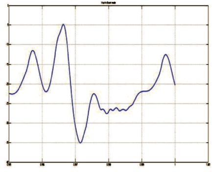
Figure 11. Output Voltage Across MIC (Fuzzy Controller)
The fuzzy logic controller used in the multi input converter decides the buffering time of each of the converter and initiates the action both in buck and boost mode according to intelligent fuzzy logic algorithm. Each of the converter was given the reference value, which was compared to the DC input value. If the reference value was found to be less than the DC input value, the MIC or the converter of that stage is supposed to operate in buck mode and if found greater, it has to be operated in boost mode respectively.
After comparing Tables 1 and 2 from the previous quantitative analysis of the response, it was found that fuzzy logic controller has the best means of minimising ripple content compared to the conventional PWM and PI control. Also effective DC bus voltage regulation, minimum settling time, improved power quality, and flexibility was achieved in case of fuzzy logic strategy.
Here a system has been proposed that will help in mitigating energy crisis by paving the path for both renewable and non-renewable sources to be interfaced together irrespective of its stochastic nature. A universal converter is developed which will multiplex all the DC input sources together and create a common DC bus bar at the output. This will establish a common DC grid system. By using intelligent fuzzy logic controller, the MIC system is self adaptive in nature irrespective of variable supply. Also it facilitates a variable duty cycle approach to each converter. The fuzzy logic control used within multi-input converter decides the buffering time of each of the duty source of the converter which will be set by firing rules under feasible relaxed boundary and so is the name given as universal converter.