Figure 1. Schematic of Intake Air Path(Panse, 2005)
In the present scenario, the optimization of engine parameters is very much necessary for the smooth operation of automotive engines. This paper presents the three Optimal Linear Quadratic Control approaches for the state space engine model for the optimization of manifold pressure and engine speed state variables. The proposed three optimal controllers are Bryson, Bouderal, and Multistage Linear Quadratic Regulator (LQR) control techniques. The proposed controllers are applied and compared for the engine state space model using MATLAB/Simulink platform.
An automotive engine, a multiple Input/output system has to satisfy a number of performance criteria under different operating conditions. During the development of Controller of an IC engine, one of the main disciplines used is control theory. An important motivation behind this study is that automatic control of IC engines lead to some of the benefits, such as improvement in fuel efficiency, power delivery as well as emission reduction. An important motivation behind this study is that automatic control of internal combustion engines leads to several benefits, such as reduction in emissions, improvement in fuel efficiency, and power delivery.
Finding of an optimized set of Engine Control Module parameters for a new vehicle is known as Engine Calibration. This is a very important aspect to be considered for the overall vehicle performance. It is an essential part of the development process of new engines and vehicles starting from the first prototypes till and even after Start of Production.
A main challenge for determining Engine calibration of complex Electronic Control Units (ECUs) are contradictory as well as tight requirements, such as NOx versus CO2 reduction. For NOx reduction, we may have to circulate Exhaust gas which in turn can reduce power and that has to be done only whenever less power is required such as in case of downhill conditions. We need to consider numerous calibration parameters here and also take into account the interactions between different software functions and Electronic Control Units. Additionally, calibrations of electronic systems vary with various types and models of the vehicles sold in different countries.
Control systems are very important in order to meet goals on low emissions and low fuel consumption to increase the performance of vehicles. Modeling, simulation, and analysis are standard tools to achieve these goals in automotive industry.
Jongeneel in 2009 has mentioned that the nonlinear model has been evaluated using the Linear Quadratic Gaussian (LQG)-controller and dynamic input allocator and he concludes that the dynamic input allocator does not improve the transient time, however, it makes the camshaft oscillation approach zero in steady state (Jongneel, 2009). Lopez et al. (2011) have developed a low cost, powerful, and robust multivariable control system based on transfer functions and also implemented and tested on two internal combustion engines (diesel and spark ignition) test beds. The control did not depend on engine or fuel type. The controller was successfully tested in a wide range of engine operating modes. It could pass through the engine non-linearities such as turbocharger turning on and some ECU points reaching the stabilization in neighboring points. The process of designing a LQR controller from a matrix of first order transfer functions with delay for engine speed and torque, met the requirements of control for engine test beds used for research activities.
Panse in 2005 has mentioned that the simulation results for the model show that it has captured peculiarities of engine behavior reasonably well. Also the simulation results for the nonlinear and linearized models are close to each other. However, small oscillations observed in case of the nonlinear system are not very well captured in the linearized version. Also the steady-state values of engine speed are slightly different for the two models, as expected (Panse, 2005). Guardiola et al. (2013) presents the methods especially the Simplified Kalman Filter (SKF) that are validated using a real world nonlinear model and sportive driving mountain profile, Sportive Driving Mountain Profile (SDMP) for NOx estimation, being an application of a high interest. They have compared the results with the ones of a gray box NOx model, obtaining similar results, which also shows the calibration capabilities of the method. Another contribution of the same researchers considering the sensor dynamics in the original state space system. The obtained results as well as the simplicity of the formulation could be the key for implementing it in HIW structures and opens the possibility of its use in commercial ECUs. Berger et al. (2011) mention that a modeling with a t-noise assumption is robust to outliers, while a modeling with normal noise assumption is not. In a practical application it is illustrated that the assumption of at-distributed noise is more appropriate than an assumption of a normal distribution for quantities of an engine, where the risk of outliers is high. Hence, online optimization for quantities of an engine which are hard to measure is now possible with this type of modeling.
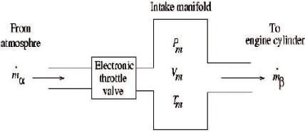
Modeling an engine in control oriented sense is an important preliminary step towards engine controller development (Panse, 2005). The model presented most of the relevant cause and effect relationships in a port fuel injection engine. Figure 1 shows the schematic of intake air path.
Figure 1. Schematic of Intake Air Path(Panse, 2005)
During the idling mode, the main objective is to maintain a constant engine speed irrespective of engine loading. The airfuel ratio is held at stoichiometric ratio by another controller. Again, the spark advance is effected by another controller (Panse, 2005). Hence, for the purpose of controlling idling speed, throttle angle (α) is the only control input that affects the production of engine torque and thus engine speed. The model has two state variables which are Manifold Pressure (Pm) and Engine Speed (ω).
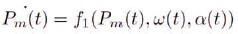
The nonlinear function of α(t), Pm(t), and ω(t) is given by,
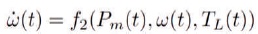
The rate of change of engine speed is to be expressed as follows:
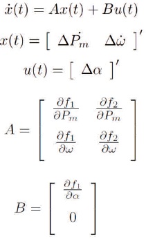
The nonlinear system is linearized and expressed in the following state-space form:
Optimal control theory is defined as searching a control law for the given optimization problem, which is in the form of quadratic to obtain some optimization solution for that particular system. Advantage of using optimal control technique compared to conventional pole placement technique is that it provides a coherent method of evaluating the state feedback control gain matrix. The optimized feedback controllers for the present research are derived from the LQR technique. For the sake of completeness, the LQR control method is explained briefly (Anderson & Moore, 2007; Skogestad & Postlethwaite, 2007; Yang & Marjanovic, 2011; Yathisha & Kulkarni, 2013).
Optimal control theory deals with the operation of a dynamic system with minimal cost. LQ problem is a case where the system dynamics are described by a set of linear differential equations and the cost is described by a quadratic function. The solution of which is provided by the Linear Quadratic Regulator (LQR), which is a feedback controller.
The equations of LQR are as given below.
Consider a Linear Time Invariant (LTI) system with
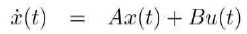
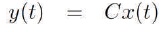
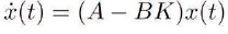
The input u is expressed as r-Kx, where r is the reference input and K is the feedback gain, also called the control law. Now assume that the reference input r is zero and that the response of the system is excited by non-zero initial state x(0), which in turn excited by external disturbances. If r = 0, then the input u =-Kx and the closed loop system is given by,
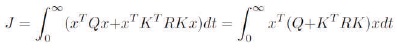
The most systematic and popular method is to find K to minimize the quadratic performance index given by,
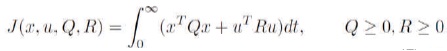
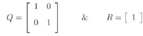
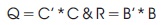
where Q and R are the positive-definite Hermitian or real symmetric matrix. The weighting matrices Q and R finds the scope of the error and the disbursement of the above mentioned performance index J. From the above equations the authors get,
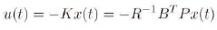
where (A, Q1/2) is detectable and (A - BK) is stable. The aim of the LQR problem is to produce a control law u = -Kx by minimizing the objective function J with the solution given by,

Thus the control law is given as,
In which P must satisfy the reduced Riccati equation:
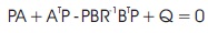
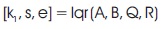
The algebraic Riccati equation can be solved using the MATLAB command lqr (Linear Quadratic Regulator).
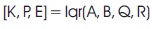
where,
K is the feedback controller optimal gain;
P is the returned solution to the algebraic Riccatti equation;
E is a vector containing the eigenvalues (eigenvalues of A-BK).
With LQR method, the engine can be replaced with another one which has totally different characteristics by doing very few adjustments on the controller parameters. Literature survey also reflects that LQR method is used for Active Suspension as well as Speed Control in the Car.
In the case study of proposed experiment, two parameters (state variables) such as Manifold Pressure and Idle Speed are considered and controlled. Intake manifold pressure plays a major role in determining the mass of air, which in turn used to determine mass of fuel to be injected to keep emission with in Control limits as per regulations stipulated by Government regulations. Also, by controlling Idle Speed, we can reduce fuel consumption to improve fuel economy which is again another Government regulation.
The optimal LQR based controllers for the engine state space model control inputs are experimented by considering the following scenarios of Bryson, Bouderal, and Multistage LQR approaches.
Bryson rule: This rule was proposed by Bryson in 1975 (Bryson et al., 1975).
Bouderal rule: This rule was proposed by Boudarel in 1971 (Bryson et al., 1975).
Multistage LQR: This technique was proposed by Pandey et al. (Boudarel et al., 1971) and is not simply selecting the Q and R matrices. It is a systematic way of designing LQR with different stages referred to as Multistage. The design procedure with different stages is as follows (Boudarel et al., 1971):
First Stage LQR: Using the Matlab command find the first stage LQR controller gain k1 from choosing the Q and R weighting using Bryson rule.
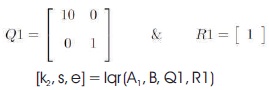
Second Stage LQR: A new state matrix A1 is obtained as A1 = A-(B*k1). With this knowledge, find the second stage LQR controller, by changing the weighting matrices as,
Third Stage LQR: A new state matrix A2 is obtained as A2 = A- (B*k2). With this knowledge find the third stage LQR controller, by changing the weighting matrices as,
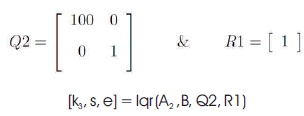
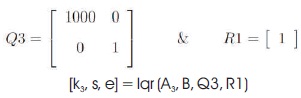
Fourth Stage LQR: A new another state matrix A3 is obtained as A3 = A-(B*k3). With this knowledge find the third stage LQR controller by changing the weighting matrices as,
The need for the design of reference input and to introduce into the engine modeling system is to get the knowledge about the transient response of the pole placement designs.
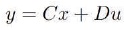
The control law is given by,

where, r is the reference input to the system.
From equation (13), it is almost clear that the system will have non-zero steady state error for the step input. In order to overcome this, let us define the control input as,
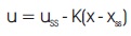
where, uss and xss are the desired final values of the state and the control input, respectively. When, x = xss (no error), u = uss.
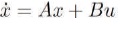
The system differential equation is given by,
In the constant steady state, equations (15) and (16) reduce to the pair,
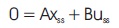
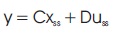
The gain calculation for the reference input is given by,
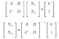
The reference input gain Nbar is given by,
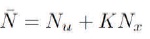
The numerical values of  for the Three scenarios (Bryson, Boudarel, and Multistage) LQR approaches are as shown in Table 1.
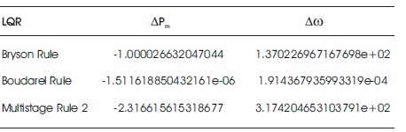
Table 1. Reference Input Gain Values for Proposed Optimal Controllers
To validate the comparison and effectiveness of proposed different optimal controllers, simulations are carried for the state variables Manifold Pressure Deviation (∆Pm) and Engine Speed Deviation (∆ω). The numerical values of A and B matrices for the nominal operating conditions of engine caliberation state space model are shown below:
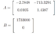
The optimized different feedback controllers obtained from optimal control LQR theory is also given below:
K =[1 274.0416]
K = [0.0028 0.5467] * 1:0e - 04
After the simulations are carried out for all the stages (four Stages), one can conclude that 2nd stage multistage LQR provides better performance compared to the remaining stages of multistage and is given by,
K = [2.3166 634.8420]
The dynamic responses of the state variables ∆Pm and ∆ω for three different LQR approaches are plotted as shown in Figures 2 - 7. Tables 2 and 3 show the comparison of peak overshoot MP and settling time Ts for three different optimal LQR approaches without step change in throttle angle (t). Comparison of MP and Ts with step change in throttle angle (t) for the proposed three optimal controllers are tabulated in Tables 4 and 5, respectively.
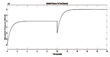
Figure 2. Manifold Pressure Deviation using Bryson Rule
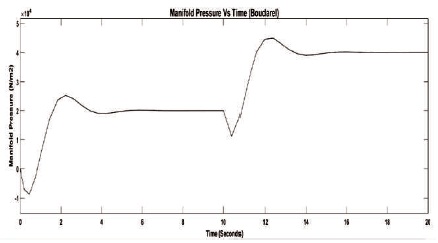
Figure 3. Manifold Pressure Deviation using Boudarel Rule
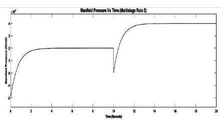
Figure 4. Manifold Pressure Deviation using Multistage Rule
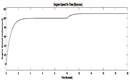
Figure 5. Engine Speed Deviation using Bryson Rule
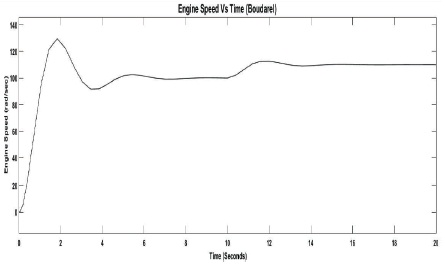
Figure 6. Engine Speed Deviation using Boudarel Rule
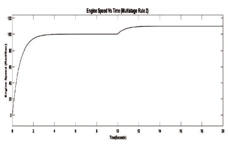
Figure 7. Engine Speed Deviation using Multistage Rule
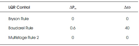
Table 2. Comparison of Peak Overshoot (Mp) for ∆Pm & ∆ω
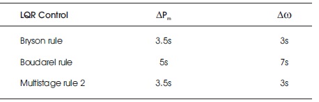
Table 3. Comparison of Settling Time (TS) for ∆Pm & ∆ω
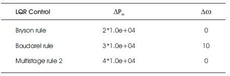
Table 4. Comparison of Peak Overshoot (Mp) for ∆Pm & ∆ω with Step Change in Throttle Angle α(t)
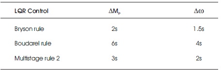
Table 5. Comparison of Settling Time (Ts) for ∆Pm & ∆ω with Step Change in Throttle Angle α(t)
The simulation results for manifold pressure deviation are as shown in Figures 2 - 4 for three different optimal LQR approaches. The results reveal that until the step change in throttle angle, the Bryson and multistage rule provides similar and better performance compared to the Boudarel rule. After the step change in throttle angle at 10 seconds, the Bryson LQR approach is the optimistic control compared to the Boudarel as well as multistage LQR approaches with respect to the system damping, peak overshoots, and settling time.
Figures 5 - 7, display the dynamic plots for engine speed deviation for the proposed three optimal LQR approaches. In this part, the results also indicate that before the step change in throttle angle, the Bryson and multistage LQR approaches provide better performance with respect to the prominent parameters of control system. After the step change in throttle angle at 10 seconds, the Bryson rule provides good damping compared to Boudarel and multistage approaches.
In this paper, the optimization of engine parameters, such as Manifold Pressure, Engine Speed is carried out by three Optimal Linear Quadratic Control approaches for the state space engine model, such as Bryson, Boudarel, and Multistage LQR control techniques. The proposed controllers were applied and compared for the engine state space model using MATLAB/ Simulink platform. The proposed control method is also compared with other optimization methods and the results reveal that better improvements are found in the proposed switching hybrid control method. The three Optimal LQR methods (Bryson, Bouderal, and Multistage) are selected for the proposed switching method because these methods provide robust stability with a minimized energy-like performance index.
A step change in throttle angle α(t) is also subjected to the system to validate and for the selection of better optimal control. The overall digital simulation results reveal that the Bryson LQR approach provides better performance compared to other LQR (Boudarel and Multistage) approaches with and without step change in throttle angle for the system. The proposed research can be further implemented for switching between individual three optimal controllers (Bryson, Boudarel, and Multistage).
The authors wish to thank Dr. Mahesh P. K., Head of Electronics & Communication Department and Dr. L Basavaraj, Principal, ATME College of Engineering, Mysore for their moral support and encouragement during this research work.
The authors also wish to thank Dr. Shankariah N., Head of Electronics & Communication Department and Dr. T. N. Nagabushan, Principal, Sri Jayachamarajendra College of Engineering, Mysore for their moral support and encouragement during this research work.