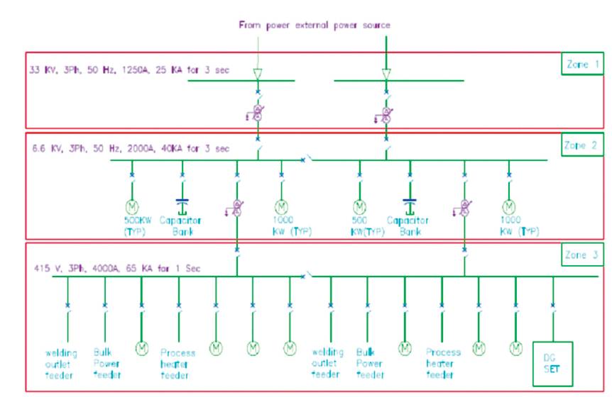
Figure 1. Typical Single Line Diagram (SLD)
Supervisory Control and Data Acquisition (SCADA) systems are widely used to automate monitoring and control of substations. Technologies such as high-speed wide area networks, Transmission Control Protocol (TCP)/ Internet Protocol (IP), switched Ethernet and high-performance low-cost computers prove to be potentially promising for increasing reliability and fostering high speed communications within the sub-station. In order to boost interoperability between Intelligent Electronic Devices (IEDs), International Electro-technical Commission’s (IEC) 61850 communication protocol has been established. With this protocol, the devices communicate with each other, thereby simplifying communication issues which were prominent in legacy substation automation protocols. A digital power grid can thus be created by implementing protection schemes modeled with communication configurations with standardized information exchange. As a result, the demand for a Substation Automation System (SAS) which provides high performance, flexibility and is simple to integrate has been fulfilled by means of IEC 61850 communication protocol.
IEC 61850 is a standard for the design of electrical substation automation. IEC 61850 is a part of the International Electro technical Commission's (IEC) Technical Committee 57, reference architecture for electric power systems. Messaging via Ethernet is employed over the conventional hardwired connections. This new standard offers a tantalizing alternative to proprietary standards and even the familiar protocol converters (Rangelov et al., 2016).
Features no other SCADA protocol has had before: Structured data, Self description and browsers, device models not data points, Capability for access security, Dramatic reduction of necessary wiring, Fast peer-topeer communications, and Powerful reporting features (Antonijević et al., 2016).
Rangelov et al. (2016) have presented the basics about IEC 61850 along with its importance from electrical engineers’ point of view. Antonijević et al. (2016) elaborated that IEC 61850 provides an explicit data model and a standardized configuration description which are greatly underutilized in today's substation automation systems. Adhikary et al. (2016) have discussed the protocol structure of IEC 61850 and the idea of using Generic Object Oriented Substation Events (GOOSE) messages for interlocking has been elaborated along with challenges of migrating to IEC 61850 from the conventional sub-station topology. It also emphasises the need of interoperability and increased communication speeds within the system. León et al. (2016) have explained the abstract data models defined in IEC 61850 are to be mapped upon application protocols, such as Multimedia Messaging Service (MMS), GOOSE, and Sampled Measured Values (SMV). These can work on high speed ethernet Local Area Networks (LANs) or TCP/IP networks.
Ali et al. (2015) have developed a communication configuration for line current differential protection and applied between two automated substations. Thus it has been proved that communication for protection by IEC 61850 between multiple sub-stations is a complex affair, yet building a robust communication network is a possibility. Matsuda et al. (2011) have described an IEC 61850 compatible SAS configuration. The paper had aimed at defining the various important aspects of the protocol like logical nodes, optional signal settings, communication services, allocation of functions to physical devices, etc. Cheng et al. (2015) elaborates how IEC 61850 provides advance communication facilities and interoperabilities in substation protection, metering, control co-ordination, monitoring, and testing. Liu et al. (2014) have evaluated the overall reliability of all-digital substation by considering various stations and processing bus topologies. Thus the most reliable Substation Communication Network (SCN) architecture has been obtained by means of reliability and sensitivity analysis. Ferrari et al. (2012) have compared some of the compact time gateways with different implementation architectures with a proof that all time gateways can be successfully applied to SAS, but some have better performance than others in terms of synchronising accuracy. Also the bottlenecks encountered in the implementation of Simple Network Time Protocol (SNTP) type of time gateway architecture has been elaborated.
A simplified Styled Layer Descriptor (SLD) on which the system design has to be implemented is selected as shown in Figure 1.
Figure 1. Typical Single Line Diagram (SLD)
A number of supporting documents are to be created such as,
It is imperative that all components to be installed in the Substation Automation System should be IEC 61850 compatible (Ferrari et al., 2012). The list of components required are elaborated as below.
Server selection is of prime most importance since it performs the functions of automatic fault recording collection, data logging, event recording, timely and informed restoring actions, etc. It is a data concentrator, protocol converter and secure access control gateway, which unifies all substation data.
The SAS interface with the operator is by means of monitors, keyboards, and mouse installed within SAS room. A portable laptop is generally used for system analysis ,configuration, parameterisation, troubleshooting, and for uploading/downloading data from relevant equipment/ devices.
The operator workstation is used for routine monitoring and control for the electrical network by authorised operator
Engineering analysis of the electrical network operations, fault analysis, and system configuration is carried out by the authorised engineer from engineering workstation.
It is an electronic device which is micro-processor controlled. It essentially interfaces objects in physical world to SCADA or Distributed Control System (DCS) by transmitting telemetry data to a master system, and by using messages from the master supervisory system to control connected objects (Dambhare et al., 2008). An RTU may consist of many circuit cards including,
An Remote Terminal Unit (RTU) may be interfaced to IEDs with different communication media and multiple master stations and may support standard protocols to interface any third party software.
Ethernet switch is a device used to build a network connection between the attached computers (establishes communication between computers). Depending on the number of relays and meters employed at each level, i.e 33 kV, 6.6 kV, and 415 V, ethernet switches with desirable number of ports are selected along with redundancy if required (Kanabar and Sidhu, 2009).
For design of given system, two types of cables are proposed.
Relays should be IEC 61850 compatible. It should have all protection needed. Redundant Ethernet port for communication should be provided. Port for IRIG B should be provided. The protective Relays should be selected for different voltage levels and should be compatible with IEC 61850 (Xu et al., 2007; Kanabar and Sidhu, 2011).
A protocol converter is a device which enables information sharing among diverse control systems using different communication standards/ protocols. It is an ideal solution for any application where connectivity with different / unsupported protocols is required. Each feeder will be incorporating meters and protocol converters with the desired number of ethernet and RS-485 ports.
The DDFR is a Digital Fault and Disturbance recording system that uses communication to retrieve disturbance, fault, and sequence of event records that are sensed by the protection relays placed throughout a substation. The critical substation information is stored inside DDFR for local station troubleshooting and also this data is archived in remote enterprise network location for permanent storage analysis.
Dedicated wiring has been used in power systems to realize time synchronization of electronic devices for distribution of Global Positioning System (GPS), Inter Range Instrumentation Group (IRIG-B), or Integrated Power Protection System (IPPS) signals. With the advent of modern IEDs capable of Ethernet communications, new methods of time synchronization based on network protocols are available (Kanabar and Sidhu, 2011). These methods are Network Time Protocol (NTP)/ Simple Network Time Protocol (SNTP) and the latest standard IEEE 1588. For the selected system, IEDs with IRIG-B inputs are proposed to be used.
Figure 11 represents the final IEC 61850 based SCADA architecture which very explicitly shows how the various SAS components are connected using the most suitable topologies and how all the specific requirements are successfully fulfilled using the latest IEC standards. Simulation of the same will outline the communication routes through the various devices and depict how control functions from the SAS are executed. RTU incorporates Ethernet Switch, Time synchronization module, I/O modules, power supply module (with redundant power supply), and controller. 415 V- UPS, Public Alarm (PA) system, Fire Alarm (FA) system, Heating Ventilation and Air Conditioning (HVAC) system and EDG system are connected through protocol converter to the Ethernet switch in RTU. Ethernet connections are via Cat 5 cables. Meters are connected to Ethernet switch through protocol converter. RTUs are connected to main Ethernet switch via Fiber Optic (FO) cables. Redundant connections of Ethernet cable, FO cable and Power supply modules are represented in different color. Time synchronization element in RTU is connected through RG- 59/58 Co-axial cables to each IED for real time data analysis. There are four main Ethernet switches. Two main Ethernet switches and RTUs are in ring topology. Other two main Ethernet switches are in tree topology with the SAS system. Ethernet switches in RTU are connected with IEDs in tree topology.
The screens of the HMI have been prepared, as illustrated in the images below. The software used for illustrating the simulation is the Flash Player.
The electrical substation automation system is shown in Figure 2.
Figure 2. Screen 1
Two buttons appear on the screen, namely “SLD” and “SAS”. We further navigate through screens by clicking the “SLD” button (Figure 3).
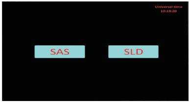
Figure 3. Screen 2
The single line diagram appears in “green” indicating that the system is not yet energized. As we click on the circuit breakers from the top (33 kV) to bottom (415 V), they close to energize the feeders which then turn “red”. This process is continued till the entire SLD gos red except the bus couplers, which are in normally open condition and it is shown in Figure 4.
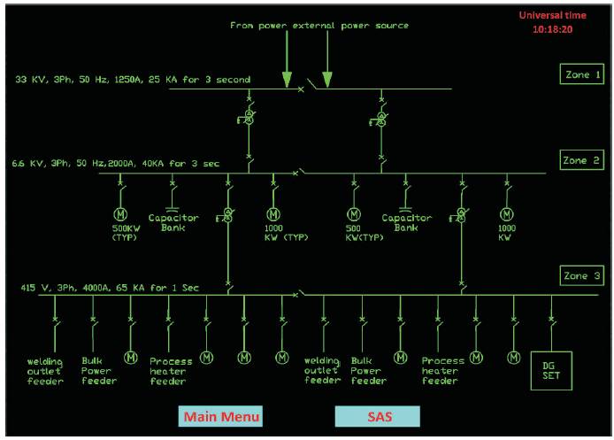
Figure 4. Screen 3
The above is immediately followed by the three zones getting highlighted as we float the cursor through the screen (Figure 5). Any of the zones, if clicked will cause the same to open up to its detailed version.
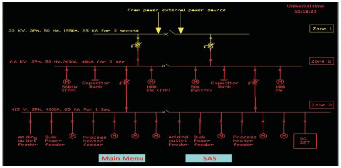
Figure 5. Screen 4
Zone 1 when clicked will open up the detailed 33 kV SLD. As we click on the “back” button, the previous screen appears. In the same way the other two zones can be opened up (Figure 6).
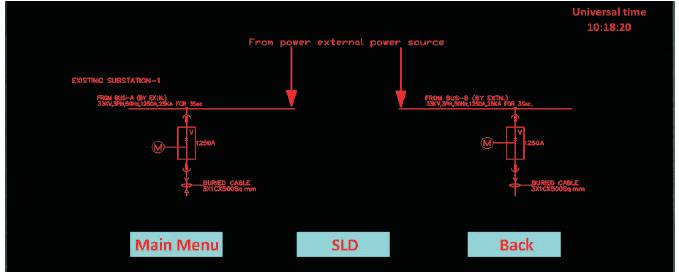
Figure 6. Screen 5
Now on clicking Zone 2, its detailed version is displayed wherein all 6.6 kV equipments are shown in Figures 7, 8, and 9. A “create fault” button is provided which when clicked causes the incomer feeder to go green and an “ALERT” indication pops up. This is closely followed by the closing operation of the bus coupler to maintain supply to 415 V bus.
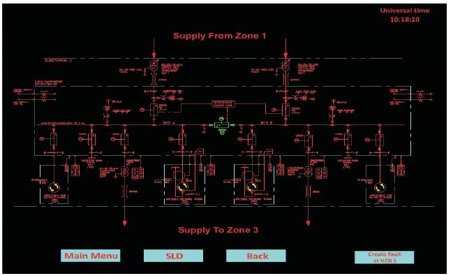
Figure 7. Screen 6 (Before Fault)
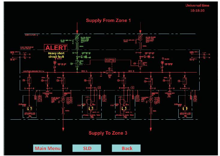
Figure 8. Screen 6 (After Fault)
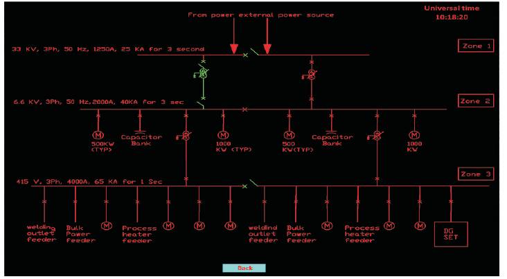
Figure 9. Screen 6 (Bus Coupler in Operation After Fault)
On clicking the feeder, the various parameters are displayed, some of which glows in red to indicate that their values have drastically changed due to the fault as shown in Figure 10.
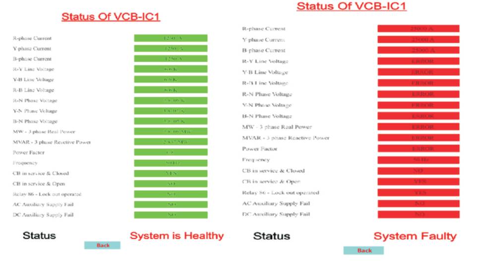
Figure 10. Screens 7
On clicking SAS, the SAS architecture is displayed, as shown in Figure 11. When we click the IED of 33 kV level, the simultaneous data flow in both directions is highlighted. Also, the precision timing signals are supplied to each IED. After clicking on IEDs of 6.6 kV and 415 V, entire data flow is illustrated (Figure 11).
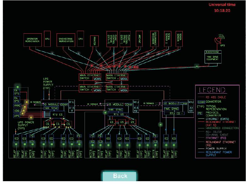
Figure 11. Screen 8
The main goal of the paper was to provide overview of the design of SCADA systems using IEC 61850 communication protocol. This supported by the screens gives an understanding of the basics of SCADA control. The present scenario shows how SCADA systems are preferred over conventional systems and how the former surpasses the latter in latest technological advances. As a result, the demand for a Substation Automation System (SAS) which provides high performance, flexibility and is simple to integrate has been fulfilled by means of IEC 61850 communication protocol.