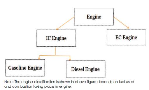
Figure 1. Classification of Engine
The engine is the heart of any hardware which may relate to various applications like Vehicles, Railway, etc. The rail application is the application where the engine will work as a main unit of the system. Cummins India Limited is the company which provides the diesel engine to various applications. The diesel engine to rail application is one of the new trends in Cummins. The modification to the railway engine and their system may give better facility to the engine. The engine is of a various type depending on their fuel consumption. The engine is classified into two types depending on which fuel is used for the engine, they are gasoline and diesel engine. The engine is further classified into two types depending on the combustion taking place in the engine, they are internal and external combustion engine. In the rail application, the diesel engine is selected because it has some advantages over the gasoline engine, where the diesel engine falls under the internal combustion type of engine. The rail application with the diesel engine further provided with the engine safety parameters will give the better rail application system. The existing system for the railway has some drawbacks which are explained in this paper and what provision necessary to be taken to provide the best system for the rail application is explained here. The existing system for the rail application consists of the display panel, the drawbacks of the existing panel, and need for the new digital display panel is also explain here.
The Engine is the family, which will consist of the main classification of the engine that is the classification depending on the working of the engine. The combustion of fuel, such as coal, petrol, and diesel generates heat. This combustion type may further classify into various types of the engine.
The engine is classified into (Internal Combustion) IC and the (External Combustion) EC. And the IC engine is further divided into Gasoline and Diesel engines and it is shown in Figure 1.
Figure 1. Classification of Engine
The working and detail information regarding the engine classification are explained in the Engine description section.
The main objective of this paper is to provide the study of the existing rail application system, the working of the existing rail engine with their parameters, and what is the need to change the system. This may lead to giving the modification to the new system for the rail application. But first there is a need to understand the overall details of the existing engine types and their working.
Thus the objective of the study is to understand the overall system. This will be explained in further sections, starting from the engine types up to their working principle and the existing methodology for rail application.
The engine is one of the main units of the system. To understand the types of the engine depending on their combustion, first the combustion taking place on the engine should be understood. The combustion is carried out in two ways: Internal and External combustion, and it is explained below.
The internal combustion is the type of the engine. The combustion takes place within the engine itself, hence it is called as internal combustion (Solovyov et al., 2017). The internal combustion converts the heat energy to mechanical energy. The diagnostics of IC engines are done to check the emissions and toxicity of it (Galiullin and Valiev, 2017). The Internal combustion classification are carried out by means of two ways:
This will classify by the intake of fuel in the engine and will divide into two main types: Gasoline/petrol engine and Diesel engine.
This classification is carried out by the operation taking place within the engine (Bingamil et al., 2017). The working principle consists of cycle of operations (Dovgyallo et al., 2017). This IC engine is of two main types: Two stroke engine and four stroke engine.
The external combustion is another type of engine combustion, where the combustion takes place by giving the external force to the system. Because of which the mechanism is occurring externally and the closed loop cycle is carried out. And this will produces the motion and the acting mechanism of the engine.
The internal combustion of the engine takes place by means of stroke and this stroke is further carried out in two types of operations: The Two stroke (Kothare et al., 2016) and four stroke operation.
In this the half revolution of crankshaft is the one stroke. The operation of two stroke has been illustrated in Figure 2.
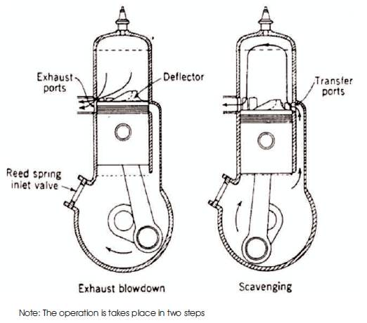
Figure 2. Two Stroke Engine
The piston is moving up compressing the fluid above it and then the new fluid is inducting.
At TDC (Top Dead Center): The ignition and after combustion.
The piston is moving down and precompressing the fluid.
At BDC (Bottom Dead Center): Precompressed fresh fuel is streaming into the cylinder and flue gas flow out.
In this the one cycle is considered to be completed after two crankshaft revolutions (Zhang et al., 2008; Bretterklieber et al., 2016). The four stroke engine is shown in Figure 3. The operation of four stroke is explained in below steps.
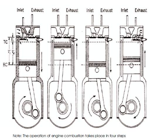
Figure 3. Four Stroke Engine, (a) Intake, (b) Compression, (c) Expansion, (d) Exhaust
The piston moves down making, the inlet valve to open for air or air and fuel mixture to flow into the cylinder.
The piston moves up closing both the valves and then the fluid inside the cylinder is compressed.
At TDC: The ignition and after combustion.
Piston moves down, and both valves are closed.
The piston moves up whereas the exhaust valve opens and the flue gas flows out.
The selection of the engine for the particular application, we requires understanding the working of the engine and the specification of the engine. The gasoline and diesel engine working are given below.
The gasoline engine is one of the type of engines, which is of the internal combustion type.
The gasoline engine consists of petrol as a fuel. The working of gasoline engine is depends on two or four stroke engine type as explained previously. The fuel and the air are premixed in the gasoline engine and hence it may lead to selfignition. The compression ratio is much higher than the diesel engine, hence it causes prone to self-Ignition. Hence the petrol engine is not used for the rail application.
The diesel engine is one of the engines which is of internal combustion type. The diesel engine has diesel as a fuel which is cheaper than gasoline. But the manufacturing cost of the diesel is more than that of the petrol engine, which is one of disadvantages of it. Hence the diesel engine (Mondal and Mondal, 2017; Mamaniyat et al., 2016) is preferable for the rail application.
The diesel engine does not pre-mixe the fuel and air, so selfignition is ignored here. Self-Ignition means the ignition taking place because of the spark generated in the engine combustion cycle by premixing of air and fuel is avoided in the diesel engine. Hence it will protect the engine life and never damage the starter of the engine which may not lead to an emergency stop of the engine. Therefore, the compression ratio of the diesel engine is compared with the gasoline engine.
The working principle (Haskara and Wang, 2013) for the diesel engine is two or four stroke depending on the mode of operations as explained in earlier sections (Li et al., 2010). Cummins provides the diesel engine with four stroke for the rail application, the operation for this is already studied in the previous section.
Stroke 1: The Fuel is injected through the injector inlet and the air is entered through the air inlet. Both the inlet is at the top. After entering into cylinder the piston goes down because of the fuel injection pressure.
Stroke 2: As every action has an equal and opposite reaction, the piston will also goes towards upper side by the Compression taking place in the cylinder.
Stroke 3: Because of the piston movement at the upper side, the ignition will take place and it will give rise to the ignition in the cylinder.
Stroke 4: Thus at the fourth step the exhaust air goes out through the outlet of the cylinder. And again piston goes down to the original position.
Thus according to the above four steps, the diesel engine will work and will provide the high-temperature, highpressure gases. Because of which it will give movement to the piston and converts the chemical energy to mechanical energy.
The Rail application uses the diesel engine because of such advantages. The diesel engine is preferable for rail applications. The diesel engine is the product of Cummins and they manufacture the engine according to the customer's requirement. Now the working is taking place on the diesel engine for the rail application with more safety parameters modification and with the more Relevant display system. This would be the future scope of this paper.
The railway application consists of the existing engine which is of diesel type as seen in the earlier section, which is a comparison between both engine types. The existing system (Okano and Kondo, 2011) in the railway has the diesel engine, but there is no safety parameters given to the engine. Hence the new system with the engine safety parameters may lead to modifications in the rail application, which would be possible if more features are added to the diesel engine and this will possible be with the digital display system as compared with the gauge display system.
The diesel engine when compact with the various sensors and the switches will provide the current condition of the engine.
Depending on the current condition, the engine will give the indications for the sensor values and for the shutdown conditions. This type of indication will be helpful to avoid the engine damage. Such type of the indications on the display panel system gives better performance of the engine in the railway.
The panel system may be of two types, namely Gauge panel or the digital display panel. The existing panel is of gauge type which has less accuracy, cheaper, but it required more number of gauges depending on the sensors required.
Some Indications are like if it will exceed the temperature range or the pressure range, it will provide an indication. If the engine is over speed than normal then it shows an indication. The result of which engine safety would be provided to the engine, which is the future scope of this paper.
To provide the indications, the condition of the engine is required and to provide all possible range indications, the display system will introduce which consists of the indication display over the panel system.
As the Gauge panel display (Figure 4) shows the gauges connected according to the requirement of sensor in the system. The area required to cover all the parameters of engine using the sensors will increase with increase in the number of sensors and hence it is the main drawback of the gauge panel display of a rail application.
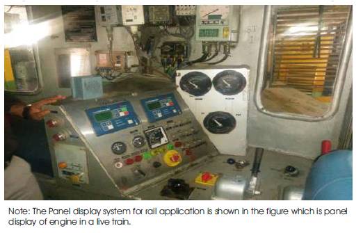
Figure 4. Existing Gauge Panel of Rail Application
The engine integration means to provide the various engine models to the rail application, so that it will produce the modified rail application system. In order to synchronize the two engine in such way it will follow the same RPM range. If the two engines are of the same train it does not follow the synchronization and the train may off the track. Hence, Integration of two engines, which are synchronized is better for the rail application.
As Cummins India Limited Company integrates various engine models for various applications that are all diesel engines (Linfeng et al., 2017).
The train with two engines in the same cabin needs to travel in synchronization. This provides a flexible working of the train and also the train with synchronized two engines never falls irrespective of the load present in the train. Hence the synchronization concept is important to apply to the rail system when two engines travel at the same time and speed.
The comparison between the two engines that is diesel and the gasoline engine have been studied. The diesel engine, which is better than the gasoline is the main conclusion and it could be used for rail applications by considering the working of the diesel engine in four-stroke operation. The existing systems of rail application by means of engine safety and the display system were also analysed. The gauge panel is not that much flexible to use in rail application, hence the conclusion is to use the digital display panel for the rail application. This digital display panel will provide more ease to the railway system. Therefore, the overall conclusion of this paper is to provide the new modified rail application system, which is more flexible, easy to implement, and synchronized compare with this existing system explained here.
The engine safety, digital display panel, and the RPM synchronization are the future scope of this work, which may increase the per formance of the engine for rail application. By adding new features of engine safety, the digital display which is more flexible than the gauge panel that consists of automotive gauge system (Liu et al., 2002) and the RPM synchronization of two engine that acts as a single unit, respectively.
This future scope will contribute to providing the better rail application system (Jo et al., 2017), the work and research on this new system for rail application are going on in Cummins India Limited, Pune.
I thank my guide Rajani P. K. for their continuous support and encouragement in this work, for enhancing me for this work and aspiring ideas in my mind. I should especially thank to Mrs. Bhairavi Patil for guiding me throughout the process. Also very thankful to Miss. Meghana Pathak being available for me any time every issues in during the process.