Figure 1. Motor Axis
Nowadays, permanent magnet machines are being popular in the industries due to its higher efficiency compared to conventional electric motors. This paper presents the modeling and simulation of three and five phase permanent magnet synchronous motor machine for healthy as well as open phase fault condition. In this paper, the crucial performance of the system has been analyzed before failure and after failure. The after effect of failures might result in costly damage and lead to another fault, if nothing is planned earlier for this fault protection. This undesirable situation ought to be averted, or at least there may be a fault tolerant function to deal with such failures. Therefore, a control scheme under an open or multiple phase fault has been discussed in this paper for multi-phase PMSM drive with sinusoidal back EMFs. In the three phase system, one phase has been kept open, whereas for five phase system, two phases kept open one by one for analysis purpose. The fault has been created only for some instant of time, after occurring fault, the PI controller compensated phase faults. Finally, it has been observed that the multi-phase machines have higher fault tolerant capability.
The applications of electric motors are growing and demand the need to improve their operating performance and efficiency. Since, the induction machine efficiency is lower and inspite of this, these machines are widely used in the industries due to its lower cost and higher availability [1, 7, 8].
Multi-phase machines are gaining attention in industries due to higher fault tolerant capability. Among the many configurations of the multi-phase systems, five-phase are suggested as a better candidate in terms of optimal design and control. These motors are an ideal option with improved torque-speed characteristics, higher torque density, reduced torque ripple, and higher reliability. Even though five-phase machines are higher fault tolerant the efficiency of the overall five-phase motor drive needs to be justified in comparison with a same rated three-phase configuration [3-6, 9, 11]. Therefore, in this paper, the five phase PMSM motor has been simulated and analyzed to verify better fault tolerance capability as compared to three phase PMSM.
Variable-speed drives are the most likely place of applications for this emerging technology, where their intrinsic properties, such as distribution of current in more than three lines, improvement in the electromagnetic torque generation for concentrated windings designs, and fault-tolerant capability can be exploited in an efficient manner [6].
Different inverter fed PMSM drive models have also been used with PMSM motor such as sinusoidal PWM inverter control fed PMSM and Space vector PWM inverter control fed PMSM. For fast response and minimized harmonics, SVPWM control is preferred [10].
From last decade, permanent magnet three phase motors considerably earned enormous popularity due to its higher efficiency compared to the other conventional electric motors. Many design and control methods are discussed to improve the efficiency of inverter-fed three-phase interior permanent synchronous motors. However, PMSM motors produce large harmonics at higher speed, the inverter side losses and core losses become prominent which eventually decreases its overall performance. Threephase permanent magnet assisted synchronous reluctance motors are special type of motors in which the magnet size has been reduced compared to other. These motors have been suggested in low cost integrated motor drive systems with higher constant power speed range. In addition, the magnet loss and core loss is reduced due to its smaller magnet size. The application of such high performance motors is equally evident in other industries, especially in electric and hybrid vehicular applications [2, 4, 8].
Since, it has been studied that the open-phase topology is the most attractive scheme because of the minimal changes required in the implementation. In this research paper, open-phase topology has been used for three and five phase PMSM machine analysis purpose. It has been concluded that the multiphase PMSM have better fault tolerant capability.
In the present time, applications of the PMSM machines are being popular in the industries due to high efficiency. As the variable speed applications are increasing in the industries, the PMSM machines are finding significant scope for variable speed applications. The significant harmonics produced by inverter can be reduced by increasing the number of phases. Therefore, in the present time, inverter fed multi-phase PMSM machines is being installed in the industries to achieve variable speed for many applications. The multi-phase permanent magnet synchronous machines may be used in the variable speed drive applications, especially in renewable energy generation.
The detailed simulation and modeling of inverter Fed PMSM motor in healthy phases is given in [8]. The model has provided accurate information of variable speed PMSM machine.
In this paper, the authors have made variable speed PMSM simulation models with open phase fault in the latest MATLAB/Simulation environment. The performance of three phase and five phase variable speed PMSM machines models with open phase fault are compared. For performance comparison, three motor parameters have been used; these are stator currents, rotor speed, and electromagnetic torque. In the simulation models, two control loops have been used for efficient performance of the motor. The inner loop is used to control the speed of the motor and outer loop is used to control stator currents. The PI controller has also been used for motor controlling purpose. Finally, the five phase variable speed PMSM motor model gives encouraging results as compared to three phase PMSM motor.
In this work, initially the authors have assumed that the motor is running with healthy phases and after some time, open phase fault has been inserted. They have opened one phase or multiple phase in the dq-abc simulation models and observed the change in the waveform. Therefore, an efficient open phase fault has been diagnosed.
From obtained results of three phase and five phase machines with open fault topology, the five phase machine having higher fault tolerant capability with good speed regulation has been observed. Therefore, in future, these models can be used in many applications, especially; inter-turn faults may also be created and diagnosed by these models.
The other aim of this present research paper is to investigate the expected results of applying symmetrical and un-symmetrical multi-phase configurations, more precisely a five-phase one, to a VSI-fed synchronous motor drive. For this reason, the structures of the five-phase motor (which is not new) and of the 5-phase VSI with PI Controller precisely chosen parameters (which is a novel topology) are presented with particular regard to their mathematical modeling features. This research paper, then shows how the controlled inverter fed five-phase motor models to be implemented in the MATLAB/Simulink environment. Finally, simulation results in normal and open phase faulty operating modes has been presented and discussed to highlight the main pros and cons of the drive topology under investigation.
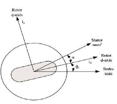
This section deals with the detailed mathematical modeling of a permanent magnet synchronous motor. The mathematical model is drawn on the basis of Park's transformation theory of resolving a 3 phase in to 2 phase d-q model. Detailed modeling of Permanent Magnet (PM) motor drive system is required for proper simulation of the system. The d-q model has been developed on rotor reference frame as shown in Figure 1. At any time t, the rotating rotor d-axis makes and angle q with the fixed stator r phase axis and rotating stator MMF makes an angle a with the rotor d-axis. Stator MMF rotates at the same speed as that of the rotor.
Figure 1. Motor Axis
The model of PMSM without damper winding has been developed on rotor reference frame by considering following assumptions:
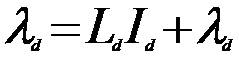
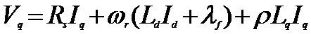
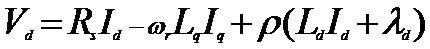
The q and d-axis voltage equations are given as follows.
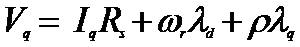
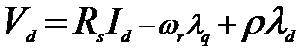
where,
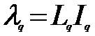
Substituting equations (3) and (4) into (1) and (2).
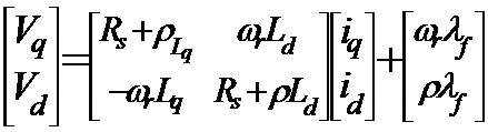
Arranging equations (5) and (6) in the matrix form,
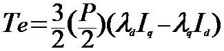
The developed electromagnetic torque in the motor is given by equation (8),
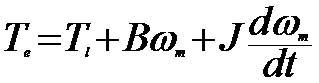
The mechanical torque equation is given by the following equation,
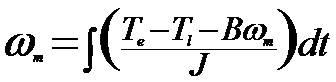
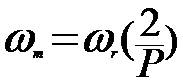
Equation (10) is solved for rotor mechanical speed.
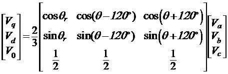
For study of motor during transient and steady state, the dynamic d-q modeling is used. For obtaining the conversion from abc to d-q, the Park's transformation is used.
Following equations are obtained on conversion of the phase voltages variables V to V variables in rotor abc dq0 reference frame,
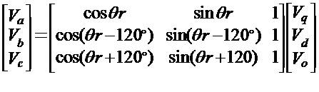
V to V conversion takes place by the following dqo abc equation,
Equations (1) to (13) give the complete mathematical modeling of the PM synchronous motor.
The complete simulation model of three phase permanent magnet synchronous machine is shown in Figure 2. The main sub models of this complete simulation model is:
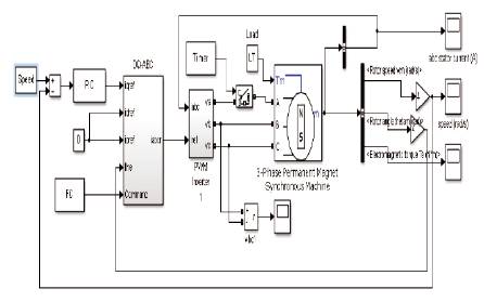
Figure 2. Simulation Model of Three Phase Permanent Magnet Synchronous Machine
The motor configurations of the use PMSM motor are,
The motor parameters of used PMSM,
The Model of PI Controller (PIC) is shown in Figure 3. The value of the Proportion (P) and Integral (I) is set at 0.4 and 3, respectively. The minimum and maximum output are set -150 to +150.
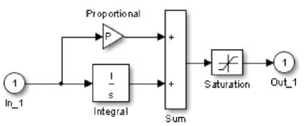
Figure 3. Model of Proportional Integral Control
The dq-abc transformation is done by the following sub model as shown in Figure 4. In the starting of the motor, it will run in the healthy phases after some set time, the phase 'a' will be opened. It will be discussed again in the result and discussion section. After, some set time; PI controller will compensate the open phase.
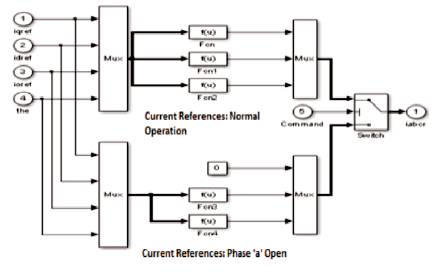
Figure 4. Model of dq-abc Transformation
The PWM inverter model is as shown in Figure 5. The PWM inverters are built entirely with standard Simulink blocks set. From Figure 5, it can be understood that the inverter output goes through controlled voltage source block before it is applied to PMSM stator winding.
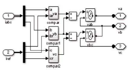
Figure 5. Model of Pulse Width Modulated Inverter
The model of the timer is as shown in Figure 6. The timer block generates a signal changing at specified transition times. This block is used to generate logical signal 0 or 1 amplitudes. Timer is used to control opening and closing times of power switches like breaker block as used in this work.
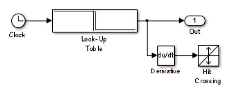
Figure 6. Model of Timer
The load torque is applied on the machine shaft is 7 Nm. This load torque is fixed in both cases, which means for three phase as well as five phase PM synchronous motor machines. In the simulation model (Figure 2), two control loops are used for regulation purpose. The inner loop is used to regulate the stator currents of the motor whereas the outer loop is used to control speed of the motor. The machine starts under all healthy phases (normal operation). The phase disconnection time is set by the timer block and available in the standard simulink block set. A circuit breaker is connected with phase 'a' will be open and closed as per instruction of timer block. The timer block is connected with circuit breaker with set time 0.06 second. It means at t=0.06 second, phase “a” will be disconnected.
Another timer is used for Fault Command (FC) operation. In this timer, the time is set 0.09 second. It means at t=0.09 second, each controller's current references are varied for compensation of phase loss.
It may be understood by the three phase stator currents, rotor speed and developed electromagnetic torque waveforms as shown in Figures 7 (a-c). It shows that at t=0.06 second phase 'a' has been disconnected and at t=0.09 PI controller compensate the phase loss. Observe the waveforms between times 0.06 second to 0.09 second; there we may observe certain disturbance if the phase “a” is open. The speed is decreased in between 0.06 second to 0.09 second. The large ripples in the electromagnetic torque are observed (Figure 7(c)).
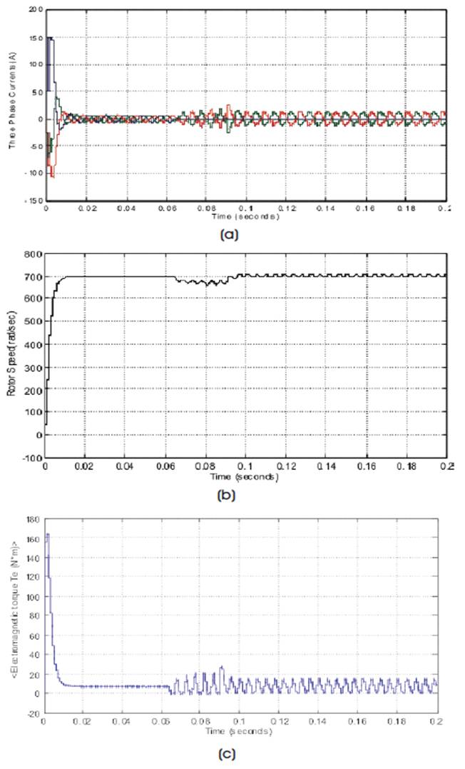
Figure 7. Signals of Motor, (a) Three Phase Stator Currents, (b) Rotor Speed, (c) Electromagnetic Torque
The result of the inverter voltage is as shown in Figure 8. From Figure 8, it is understood that the rated DC voltage is achieved, i.e. 300 Volt. This voltage is achieved in phase 'bc'. From this figure, it has been observed that, upto 0.06 second the pulse widths are uniform, but after 0.06 due to phase 'a' open pulse widths obtained are unequal.
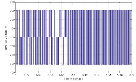
Figure 8. Line-to-Line Voltage in Phases bc
The complete simulation model of five phase permanent magnet synchronous machine is shown in Figure 9. The motor configuration and parameters are same as discussed for three phase permanent synchronous machine.
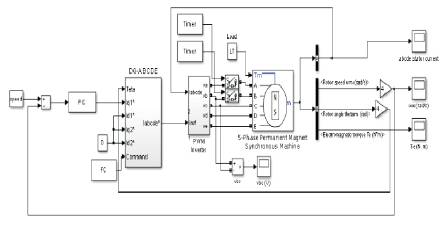
Figure 9. Simulation Model of Five Phase Permanent Magnet Synchronous Machine
The Model of PI Controller (PIC) is shown in Figure 10. The value of the Proportion (P) and Integral (I) is set at 20 and 11, respectively. The minimum and maximum output is set -150 to +150.
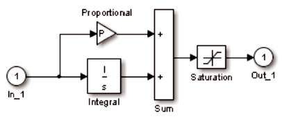
Figure10. Model of Proportional Integral Control
The dq-abc transformation is done by the following sub model as shown in Figure 11. In the starting of the motor, it will run in the healthy phases. The faulty phase will be considered for two cases; first phase 'a' open and second phase 'a' and 'b' open. It will be discussed again in the result and discussion section. After, some set time; PI controller will compensate loss due to open phases.
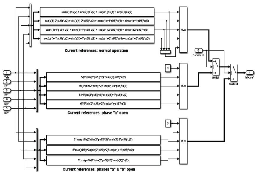
Figure 11. Model of dq-abc Transformations
The PWM inverter model is as shown in Figure 12. The PWM inverters are built entirely with standard Simulink blocks set. From Figure 12, it may be understood that the inverter output goes through controlled voltage source block before it is applied to PMSM stator winding.
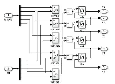
Figure 12. Sub Model of Pulse Width Modulated Inverter
The sub model of timer is as shown in Figure 6. The same timer sub model will be used here for five phase PMSM analysis purpose. In the five phase machine, three timers are used to perform an specific function for system. The timer block generates a signal changing at specified transition times. This block is used to generate logical signal 0 or 1 amplitudes. Timer is used to control opening and closing times of power switches like breaker block as used in this work. In the five phase machine, two circuit breakers are used to open phase first only phase 'a' and second phase 'b' in different timings. This open phase fault analysis will be discussed in the subsequent section.
The load torque applied on the machine shaft is 7 Nm. The same fixed load torque is used for three phase machine as well as five phase machine. In the simulation model (Figure 9), two control loops are used for regulation purpose. The inner loop is used to regulate the stator currents of the motor whereas the outer loop is used to control speed of the motor. The machine starts under all healthy phases (normal operation). The phase disconnection time is set by the timer block and available in the standard simulink block set. A circuit breaker is connected with phase 'a' will be open and closed as per instruction of timer block. The timer block is connected with circuit breaker with set time 0.06 second. It means at t=0.06 second, phase 'a' of machine will be disconnected. The phase 'b' circuit breaker is used for phase 'b' and time needed to open this phase is set 0.12 second.
Another timer is used for Fault Command (FC) operation. In this timer, the time is set 0.09 second and 0.15 second. It means at t=0.09 second and t=0.15 second, each controller's current references are varied for compensation of phases loss.
It may be understood that, by the three phase stator currents, rotor speed and developed electromagnetic torque waveforms are as shown in Figures 13 (a-c). It shows that at t=0.06 phase 'a' has been opened and at t=0.09 PI controller compensates the phase loss. The waveforms are observed between 0.06 second to 0.09 second; there one may observe certain disturbance as the phase “a” is open. The speed is decreased in between 0.06 second to 0.09 second. The ripples in the electromagnetic torque are observed (Figure 13(c)).
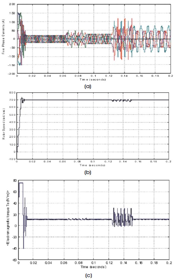
Figure 13. Signals of Motor, (a) Three Phase Stator Currents, (b) Rotor Speed, (c) Electromagnetic Torque
In the next case, phases 'b' is also disconnected. The phase 'b' is disconnected in the five phase machine at time t=0.12 second. At t=0.15 second, for compensation of the two phase loss, the controller's current references in the five phase machine used. One may understand this analysis from obtained waveforms of the motor as shown in Figures 13(a-c).
The result of the inverter voltage is as shown in Figure 14. From Figure 14, it is understood that the rated DC voltage is achieved, i.e. 300 Volt. This voltage is achieved in phase 'bc'. From this figure, it has been observed that, upto 0.06 second the pulse widths are uniform, but after 0.06 due to phase 'a' open pulse widths obtained are unequal. The phase 'a' is disconnected at 0.06 second and phase 'b' also disconnected at 0.12 second time. The PI controller compensated phase loss after 0.15 second. Therefore, between 0.12 second to 0.15 second distorted pulse widths are obtained.
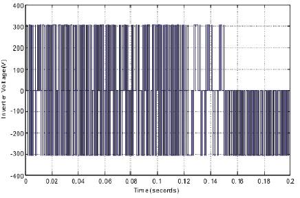
Figure 14. Line-to-Line Voltage in Phases bc
Therefore, after observing the results of three phase machine and five phase machine, it is known that the five phase machine gives better results as compared to three phase machine. The five phase machine has shown higher fault tolerant capability. Therefore, in future multi-phase machines will be preferred in the industries for efficient performance.
In this research paper, the modeling and simulation of three and five phase permanent magnet synchronous motor drives for healthy as well as open phase fault topology has been discussed. From the obtained results of three phase and five phase machines with open fault topology, it can be concluded that the five phase machine has higher fault tolerant capability. It has been observed that, due to the change of current references during the two successive faults, the currents of the five phase machine has been increased to keep the electromagnetic torque at the same value for prevention of large ripple. Good speed regulation has also been observed in the five phase machine as compared to three phase machine. Therefore, finally, the authors conclude that the five phase machine is having much more efficiency and fault-tolerant capability than the three phase machine.