[1]
A Photovoltaic PV module along with an interconnection which gives a proper voltage and current to charge rechargeable batteries is termed as PV Battery Charger. The interconnection system used is a DC-DC converter which provides suitable charging voltage and current to the battery. Maximum Power Point Tracking is very unique to the field of PV systems to extract maximum power during operation. There are many conventional methods available for Maximum power point tracking, but they fail under rapidly varying weather conditions. To overcome this problem, non linear controllers are utilized much in the field of photovoltaic system. In this paper, the Sliding Mode Controller is implemented as the MPPT algorithm to deliver maximum power even under rapidly varying environmental conditions, disturbances, and system uncertainties. The obtained results indicate that the Sliding Mode Controller provides robustness under varying weather conditions compared to the conventional MPPT algorithms.
The renewable energy sources, such as solar energy, wind energy, and fuel cells are being utilized more because of the effect of global warming and the receding conventional energy sources. In accurate, solar PV energy has been widely used in many applications, such as solar thermal electric power plants, photovoltaic, solar heating systems, solar lighting, and solar electric vehicle. There are many advantages offered by solar energy than traditional sources of energy like coal and oil. Maximum power point tracking or commonly known as MPPT is very unique to the field of PV systems and this also brings about a very special application of power electronics in the field of photovoltaic.
A comparative analysis of four types of MPPT is given in [12]. The MPPT methods chosen in this paper are Hil Climbing (HC) method, Perturb and Observe (P and O) method, Incremental Conductance (IC) method, and Fuzzy Logic Control MPPT. The simulation response for all these MPPT techniques is obtained under rapidly var ying environmental conditions. Sliding mode control algorithms for buck and boost power converters are surveyed in the paper along with sliding surface equations and derivation of equivalent control. Reduction in chattering done by harmonic cancellation is demonstrated in [13]. The sliding mode control to accomplish fast tracking speed and reduced steady state oscillation is given. Moreover, unlike other methods which require feedback signals from voltage and current sensors, this strategy just requires current to produce control actions. The benefits of this sliding mode control is simple implementation and it can achieve both high tracking speed as well as reduced steady state oscillation discussed by [15]. The sliding mode controller is robust in steady state as well as under differing weather conditions. The controller can be utilized as a control actuator for the MPPT algorithm proposed in [4]. The terminal sliding mode control overcomes the singularity problem present in traditional sliding mode control was presented in [3]. The integral sliding mode control together with the MPPT current controller is applied for the regulation of current is proposed in [3]. The control algorithm consists of two loops, one for estimating the maximum power voltage which is used in second loop as a reference value for backstopping sliding mode control is proposed in [5]. Better voltage regulation is attained even under changes in online voltage and input parameters keeping load as constant is discussed in [1].
The major problem that is to be concentrated in the field of solar energy is that its heavy dependence on they are not robust to disturbance, uncertainties, and rapidly changing environmental conditions. So here comes the role of non linear controllers to extract maximum power even under disturbances and varying weather conditions [6], [9]. Charging a battery with no interface devices between PV panel and battery makes damages in the battery [4] and thus reducing the life cycle of battery. Also the current entering the battery should be regulated.
The PV module is the interface which changes over light into power. Modelling this fundamentally requires taking climate information (irradiance and temperature) as input parameters. The resultant can be current and voltage where the product gives the power. Any adjustment in the sections instantly infers changes in output. That is the reason, it is imperative to utilize an exact model for the PV module [2].
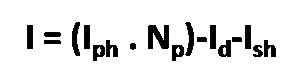
Load current:
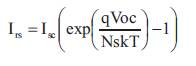
Reverse saturation current Load current:
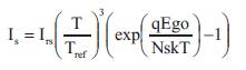
Reverse saturation at operating temperature:
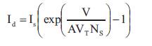
Diode current:
Thermal Voltage:

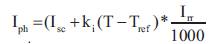
Phase current:
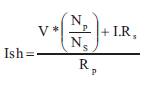
Shunt current:
where,
I is light generated current
I is diode current
I is shunt current
E is semiconductor band gap energy
T is reference temperature
T is PV module temperature
I is short circuit current
V is open circuit voltage
I is reverse saturation current
V is voltage imposed on diode
V is thermal voltage
k is Boltzmann's constant
q is charge of an electron
Among several nonlinear controllers, several benefits are offered by Sliding Mode Control (SMC), which has large signal stability, reduction in system order, and less implementation.
The solar cells are interconnected in a series-parallel combination to achieve the desired power because a single Photovoltaic cell produces less voltage and current. The desired voltage is produced by interconnecting the solar photovoltaic cells in series and the desired current is generated by associating the cells in parallel. The above equations are mathematically modelled in MATLAB Simulink to get the PV current and voltage.
DC-DC converters, for example, buck converter, boost converter, and buck-boost converter have been broadly utilized as a part of conventional modern applications, for example, uninterruptible power supply, DC motor drives, power systems, equipment for telecommunication, and so forth [14]. Boost converter also known as step up converter is chosen to boost the input panel voltage to a higher voltage.
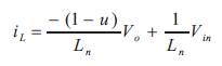
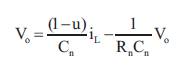
Figure 1 comprises of inductor that allows panel current, switch (MOSFET), which is controlled by the sliding mode controller, diode, capacitor, and load resistance [8]. With respect to the duty cycle, by using the following design equations the output voltage can be evaluated.
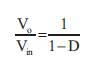
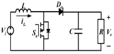
Figure 1. Circuit Diagram of Boost Converter
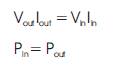
The product of output voltage and current is equivalent to product of input voltage and current in an ideal circuit, i.e
3. Calculation of Inductance and Capacitance
The value of the inductor and capacitor of the converter can be designed as follows.
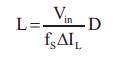
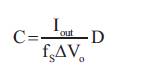
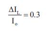
where f is the switching frequency, I is the input current s L ripple, and V is the output voltage ripple. The proportion 0 between the input current ripple and the current output of the converter is known as the ripple factor. The current ripple factor should lie within 30% for a good design of inductor.
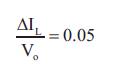
The maximum output current should always be less than that of the current rating of inductor. The value of V is o normally taken as 0.05 times the output voltage, i.e
The design specifications for the converter are V =20 V, in V =40 V, and f = 20 KHz. From this, inductor, capacitor, and o s resistor values can be determined.
The outline of Sliding Mode Control for the most part contains two stages: The initial step is to design the sliding surface, and the second step is to design the control signal. The sliding surface is chosen according to the applications that have to be controlled. By then, the control signal is intended to ensure the presence condition. The sliding mode control is designed as in [10].
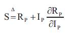
The derivative of the panel power with respect to the panel voltage is selected as the sliding surface.
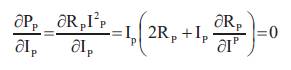
where, R =V /I . Consequently, when panel current and p p p converter output voltage (state variables) converge to the sliding surface, the power from the panel will be boosted. The sliding surface is chosen as follows,
The control signal is defined by,
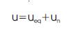
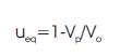
where, u is the control signal, u is the control derived by eq equating the derivative of sliding surface to zero, and u is n the control designed to neglect the effect of perturbation and to force the states of the system towards the sliding surface [10]. The objective of the equivalent control is to guarantee that the system trajectory remains.
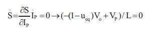
From this,
The curbing control is defined as follows,

where, h>0, k>0 and d>0 are constants. The control 0 amplitude depends on the sliding surface.
Initialize parameters ( k, d , h );
Δt → Sampling Period;
while (1) do
Measure V (t), I (t), V (t);
Step 1: Calculate the resistance of panel, R (t)
Step 2: Calculate change in R and change in I p p
Step 3: Implementation of sliding surface
Step 4: Design of equivalent control by equating s to zero
Step 5: Design of curbing control
Step 6: Design of Control signal with equivalent control and curbing control.
Step 7: Condition checking for the control signal
end
end
By implementing the above algorithm in MATLAB code, the duty ratio of the Boost converter is controlled according to the control action taken.
In this paper initially the PV panel is designed to provide the voltage source to the Boost Converter. The boost converter is designed in such a way that it regulates the PV current by acting as an interface between the PV panel and the Battery.
The most common MPPT algorithm used is Perturb and Observe (P and O) method. The advantage of this method is that accuracy is more and has faster response. This type of MPPT directly measures the voltage and current or power as well. The major drawback of this method is that the operating point oscillates at maximum power point. Also this method struggles at rapidly changing irradiance.
The simulink model of the Perturb and Observe method is shown in Figure 2. Here the panel voltage and panel current is sensed by the Perturb and Observe MPPT algorithm and the duty cycle is given to the gate pulse of the Boost converter. After sensing the voltage and current from the panel, this algorithm first filters the signal and then samples. The product of voltage and current yields the power. The memory block stores the value of V and I once the value changes. Afterwards del P and del V is calculated and checked for the condition. Then according to the increase or decrease in the signal, the duty ratio is generated and given to the gate pulse of the IGBT.
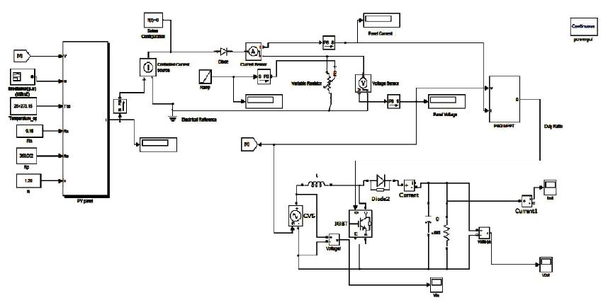
Figure 2. Simulink Model of the Perturb and Observe MPPT algorithm
The voltage waveform of the Boost converter with P and O under constant irradiance and constant temperature is given in Figure 3, which shows the output voltage of the boost converter is 37.94 Volts.
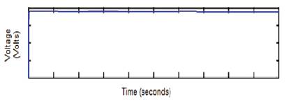
Figure 3. Voltage Waveform of Converter
When the irradiance variation is given, this method delivers maximum power, but it is not robust to irradiance variations. So this method is not applicable for rapidly changing environment. The sliding mode controller overcomes this problem effectively. When the irradiance varies from 1000 2 2 KW/m to 700 KW/m at 0.1 second, the panel voltage drops from 21.05 Volts to 20.01 Volts. The effect of change of irradiance is shown in Figure 4.
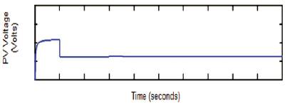
Figure 4. Voltage Waveform of PV Panel with Change in Irradiance
When the irradiance changes the P and O method is unable to track the changes in the PV panel voltage as well as current. The voltage waveform of the converter is shown in Figure 5. It is clear that Perturb and Observe method delivers maximum power even if the irradiance varies, but it is not robust to irradiance changes.
Figure 5. Voltage Waveform of PV Panel with Change in Irradiance
Figure 6 shows the simulink model of sliding mode MPPT algorithm. The panel voltage and panel current is given to the sliding mode controller. The sliding mode control also receives output voltage of the boost converter. According to the control signal generated, the duty ratio is calculated and given to the gate of the IGBT.
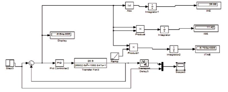
Figure 6. Simulink Model of the Battery Charger using PID Controller
The state of charge of the battery during the simulation is shown in Figure 7. The current and voltage of the boost converter enters the battery for charging. The voltage waveform of the Boost converter with SMC under constant irradiance and constant temperature is given in Figure 8. The output voltage of the boost converter is 39.22 Volts.
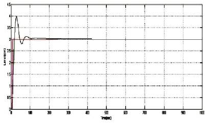
Figure 7. Response for Battery Charging using PID Controller
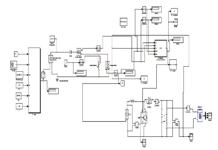
Figure 8. Simulink Model of the Battery Charger using Sliding Mode MPPT Control
The PID (Proportional Integral Derivative) control is one of the earlier control strategies. It has a simple control structure for battery charging applications.
Figure 7 represents the saturation used in the simulation to ensure that the control signal always remain within the bound. The value of tuning parameters used in the simulation results is k= 1200 and d=0.15. Figure 9 shows the State of Charge of the Battery using Sliding Mode MPPT Control and Figure 10 represents the Voltage waveform of the converter using Sliding Mode MPPT Control.
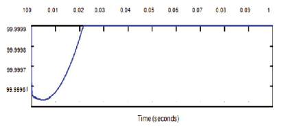
Figure 9. State of Charge of the Battery using Sliding Mode MPPT Control
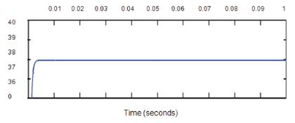
Figure 10. Voltage Waveform of the Converter using Sliding Mode MPPT Control
The irradiance varies between 1000 and 700 (W/m ), while the temperature and load are maintained at constant (T= 25 °C and R=150 ohm). In the simulation, robustness of the system is checked by varying irradiance. From Figure 12, it can be concluded that this method provides robustness towards the insulation variation. Thus the battery is charged efficiently even during environmental variations. The state of charge of the battery during the simulation is shown in Figure 11. The current and voltage of the boost converter enters the battery for charging. The battery is charged efficiently even when the irradiance changes. When the irradiance changes the sliding mode MPPT is able to track the changes in the PV panel voltage as well as current. The voltage of the converter drops from 39.22 to 38.88 Volts. When the irradiance changes the sliding mode MPPT is able to track the changes in the PV panel voltage as well as current.
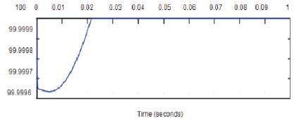
Figure 11. State of Charge of the Battery using Sliding Mode MPPT Control with Change in Irradiance

Figure 12. Voltage Waveform of the Converter using Sliding Mode MPPT Control with Change in Irradiance
Table 1 shows the simulation conditions of sliding mode MPPT control. It is clear that when the irradiance changes during operation, the output voltage of the converter changes according to the change in irradiance level. Thus the sliding mode controller is robust to the change in irradiance level
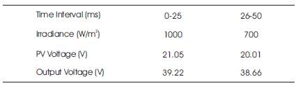
Table 1. Simulation Conditions for Sliding Mode controller
Based upon the above analysis the sliding mode controller and PID controller performance was measured (Figure 13).
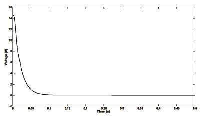
Figure 13. Control Effort of Sliding Mode Control (SMC) with PID Control
Based on the error analyses, control effort and observation on the tracking performance, the SMC provides more convenient and better performance in tracking of changes in irradiance control and ensured that the control system in under stable condition as in Table 2.
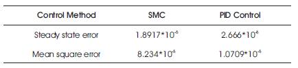
Table 2. Error Analysis for SMC and PID Controller
The Photovoltaic based battery charger is designed using a sliding mode MPPT controller in this paper. The robustness of the controller against irradiance changes are verified by the simulation results. The robustness are checked for both Perturb and Observe MPPT algorithm and Sliding mode MPPT algorithm by giving irradiation changes during the operation. The stability of the system is attained by using Lyapunov theory. Simulation results show that while PO algorithm is not able to detect the changes in irradiance, the SM MPPT is capable of detecting the variations and gives the converter voltage effectively. Hence, it is concluded that Perturb and Observe method is not robust to irradiance changes, but the sliding mode controller proves to be robust towards irradiance changes.