[1]
This paper deals with the stability analysis of three-phase Induction motor drive using three stability criteria, namely Root locus, Bode plot, and Nyquist plot. etc. of the control system. The dynamic model of three-phase induction motor drive is designed. This model has been derived using two-phase motor in direct and quadrature axes. This approach is desirable because of the conceptual simplicity obtained with a two sets of windings, one on the stator and other on the rotor. The required transformation in voltages, currents, or flux linkages are derived in a generalized way. The mathematical equations so obtained are non-linear in nature. The mathematical model used is linearized around an operating point using the perturbation technique. The transfer function of three-phase induction motor drive is determined at different rotor frequencies and hence rotor speeds. The effect on stability of the drive is assessed at different frequency conditions. The rotor frequency (f ) and hence corresponding speed (w =2πf ) at which the drive is unstable is reported. This analysis is r r r carried out using MatLab codes.
Three-phase induction motors are most widely used motors in household and industrial applications. These motor drives are also widely used in applications, such as pumps, fans, elevators, paper mills, electrical vehicles, textile mills, servo, wind generation systems, steel mills, cement mills, etc. Induction machines were introduced more than one hundred years ago. An engineer designing a high performance drive system must have intimate knowledge about machine performance. M.O. Dolivo-Dobrovsky, a Russian engineer, invented a three-phase Induction motor and three-phase transformer in 1889. Later on (in 1890) he developed a three-phase induction motor with a slip ring rotor in to which resistor were connected for starting and control. Stability is very important characteristic of an induction motor which provides the reliability of the work. For stability analysis, the dynamic model of the induction motor is derived by using a two phase motor in d-q axes. This approach is desirable because of the conceptual simplicity obtained with two sets of windings, one on the stator and one on the rotor. This approach is suitably extended to an n-phase machine model by means of a two phase machine. The power rating of the machine must be equal in the three-phase machine and its equivalent two phase model. The reference frames chosen to arbitrary, such as stationary rotor and synchronous reference frames. For the sake of completeness, the space phasor model is derived from the dynamic model in direct and quadrature axes. It is assumed that the d-axis is leading the q-axis for clockwise direction of rotation of the rotor. If the clockwise phase sequence is dq, the rotating magnetic field will be revolving at the angular speed of the supply frequency, but counter to the phase sequence of the stator supply [3], [7-9], [13-15].
The rotation of rotor relative to stationary stator is considered in the derivation of mathematical models, describing the behavior of induction motor drive. Different coordinate systems can be used for this purpose. The common coordinates are the fixed frame, connected with stator, and the rotating frame, connected with rotor. The fixed frame was first used by Stanley [16]. The rotating frame was obtained by applying Park's transform [12] to induction motor in (Brereton et al., 1957) [10]. Fallside and Wortley [6] has analyzed the instability of induction motor fed by variable frequency inverter, neglecting the effect of harmonics. MacDonald and Sen [11] also developed a linearized model of current source inverter induction motor to study the stability. Nyquist stability criteria was used by Lipo and Krause [10] to study the stability of a rectifierinverter induction motor drive neglecting stator voltage harmonics. Stability study of controlled current induction motor drive based on transfer function technique was also carried by Cornell and Lipo [5].
All the above studies carried out so far are based on voltage-current relationship. If the stability analysis of threephase induction motor drive is carried out by driving the d-q voltage-flux linkage model, number of variables used are reduced. With the reduction of variables the solution of the dynamic equations can easily be achieved using analog and digital computers. Based on voltage-flux linkage model, Alam et al. [2] developed a dynamic model of fivephase induction motor to evaluate the performance of the drive utilizing the conventional techniques, such as Root locus, Bode plot, and Nyquist plot of control system. The developed model of five-phase induction motor was linearized in d-q variables in synchronously rotating reference frame. The transfer function was obtained between the stator frequency and load torque corresponding to rotor frequency. Alam and Khan [1] have also developed the dynamic model of five phase induction motor drive system. The transfer function technique has been used to determine the stability of five phase induction motor drive. The performance analysis of five phase induction motor drive is based on different stability criteria, such as Bode plot, Nyquist plot, and Root locus. The transfer function between the stator frequency and hence stator speed (w =2πfs) and the rotor frequency, s f and hence rotor speed (w =2πfr rad/sec) is obtained and r r the stability study of the motor drive is reported at different rotor frequencies.
Based on the transfer function technique utilized by Alam et al. [1] the stability analysis of three-phase induction motor drive is reported in this paper. This model which is based on voltage-flux linkage is simple linearized model used for the stability analysis of three-phase induction motor drive. This model can also be used for high phase induction motor drive system under steady state and dynamic conditions.
Stability Analysis is one of the most important parameters to determine the performance electric drive system. The major objectives of this research paper are:
The induction motor dynamic equations can be represented by flux linkages as variables in arbitrary reference frame. The number of variables in the dynamic equation of voltage-flux linkage induction motor model reduces, which greatly simplifies their solution by using analog and digital methods. The flux linkages are continuous in nature even the voltages and current are discontinuous. The numerical stability of induction motor derived is achieved using this model. To highlight the process of decoupling of flux and torque channels in the induction and synchronous motors, the flux linkage representing is applied with the drive.
The equations of stator and rotor flux linkages in the arbitrary reference frames are written as:
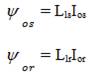
The zero sequence flux linkages are,
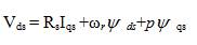
The q-axis stator voltage in the arbitrary reference frame is

Substituting from the defined flux-linkages into the voltage equations yield
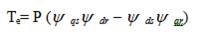
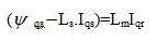
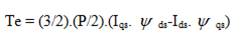
These equations can be represented in equivalent circuits. The electromagnetic torque in terms of flux linkages is given by,
The rotor currents can be substituted in terms of the stator currents and stator flux linkages from the basic definition of the flux linkages used in equation (1). From equation (4),
Hence,

Similarly,
Substituting equations (6) and (7) into equation (4) gives the electromagnetic torque in stator flux linkages and currents as,
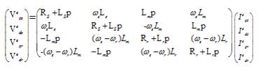
The induction motor model in terms of the flux linkages described in above section is made use of in this section. The relation between voltage and flux Linkages can be found by expressing the currents in terms of flux linkages. To derive the relation first we have to specify the voltages, currents, and flux linkages vectors in an arbitrary reference frame. Suppose the speed of reference frame is w = w, c s Stator supply angular frequency in rad/sec and q= q in c s radians.
The relation between the voltage and current is given by,
And the relation between flux-linkage and the current is given by,
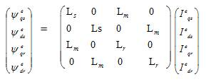
This on simplification provides,
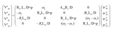
which is the required relation between the flux-linkage vector and the applied voltage across the induction motor expressed in the d-q axis form.
The control characteristics of an induction motor drive consist of its stability characteristics and its frequency and time responses. Evaluation of control characteristics requires determination of various transfer functions of the drive. The stability study of a three- phase induction motor drive has been performed by applying the Eigenvalues stability criterion to the small displacement equations obtained by linearization about an operating point. At first model of motor drive is developed in the state variable form. This is followed by the determination of eigenvalues of the system matrix 'A'. The voltages, currents, torque, stator frequency, and rotor speed in their steady state are designated by an additional subscript 'o' in the variables and the perturbed increments are designated by a d preceding the variables and used as coefficient. Accordingly the motor drive variables after perturbation are
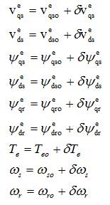
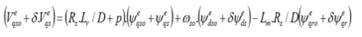
The standard perturbed voltage and flux linkage vector equations in dqo frame:

Application of perturbation technique yields the following state variables form as,
On further simplification, we get,

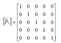
Equation (15) can be written in compact form as,
where,
Here unit vector is represented by [U’] and the state vector is represented by [X’].

where,
and
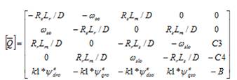
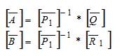
The system matrix is written as,
where,
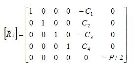
The system matrix can be written as follows,
where,
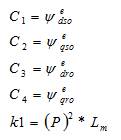
The second, fifth and sixth column of matrix [R’ ] is because of 1 the terms dV , dw, and d, respectively. The other input dso s TL voltages are assumed to be zero. The output of the machine is represented in terms of incremental flux linkage, incremental torque, and incremental speed. The response of motor drive due to one of the parameter changes (voltage, load torque or synchronous speed) is incorporated. One of the quantities is changed at a time. The incremental output flux linkage, torque, and speed vectorsa written as,
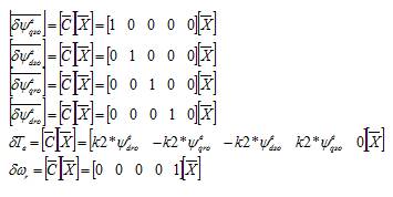
where,
The parameters of the three-phase induction motor drive used for simulation are given in the appendix section. Following are the transfer functions obtained at different rotor frequencies and hence rotor speeds.
Transfer function:
Transfer function:
Transfer function:
Transfer function:
Different operating conditions has been selected to carry out the stability analysis of three phase indiction motor drive. The four operating conditions selected for analysis are f =50 Hz (w=314 rad/sec), f =45 Hz (w= 283 rad/sec), r r r r f = 40 Hz (w= 251 rad/sec), and f = 37 Hz (w= 232 rad/sec). r r r r The transfer function corresponding to these frequency has been obtained above. Stability analysis based on these transfer functions is carried out using different stability criteria, such as Bode plot, Nyquist plot, and Root Locus. The different plots so obtained has been drawn in Figures 1, 2, 3, and 4, respectively.
The step response corresponding to these frequencies is drawn in Figure 1. It is clear from the figure that with the decrease in rotor speed, the stability margin goes on decreasing. It takes large time to reach to the stable point and settles there. At frequency 37 Hz the three phase induction motor drive reaches to unstable point which is indicated in Figure 1(b). So at frequency 37 Hz the three phase induction motor drive becomes unstable. The Bode diagram is shown in Figure 2, in which the phase margin and gain margin both are positive for f = 50 Hz, 45 Hz, and r 40 Hz, respectively, which indcates the stable operation of the drive dystem. But at f =37 Hz, the phase margin is r positive but the gain margin is negative, which is the clear indication of the unstable operation of the drive. In Figure 3, Nyquist plots for different frequencies has been drawn. For frequencies 50 Hz, 45 Hz, 40 Hz, the rotation is in clockwise direction and no encirclement of (-1, 0) and there is no closed loop pole in the R.H.S. of s-plane. Hence the drive is stable for these frequencies. For f =37 Hz, the rotation is in r counter clockwise direction and no encirclement of (-1,0). There is a closed loop pole in the R.H.S of s-plane so the drive is unstable for this frequency condition. Root locus diagram corresponding to f =50 Hz, 45 Hz, 40 Hz, and 37 r Hz so obtained has been drawn in Figure 4. For first three frequency conditions all the poles lies in the L.H.S. so the three phase induction motor drive is stable for these frequency conditions but for f =37 Hz, one pole crosses the r L.H.S. and reaches to R.H.S. which is clearly seen in Figure 4(d). So the drive is unsatable for this frequency condition.
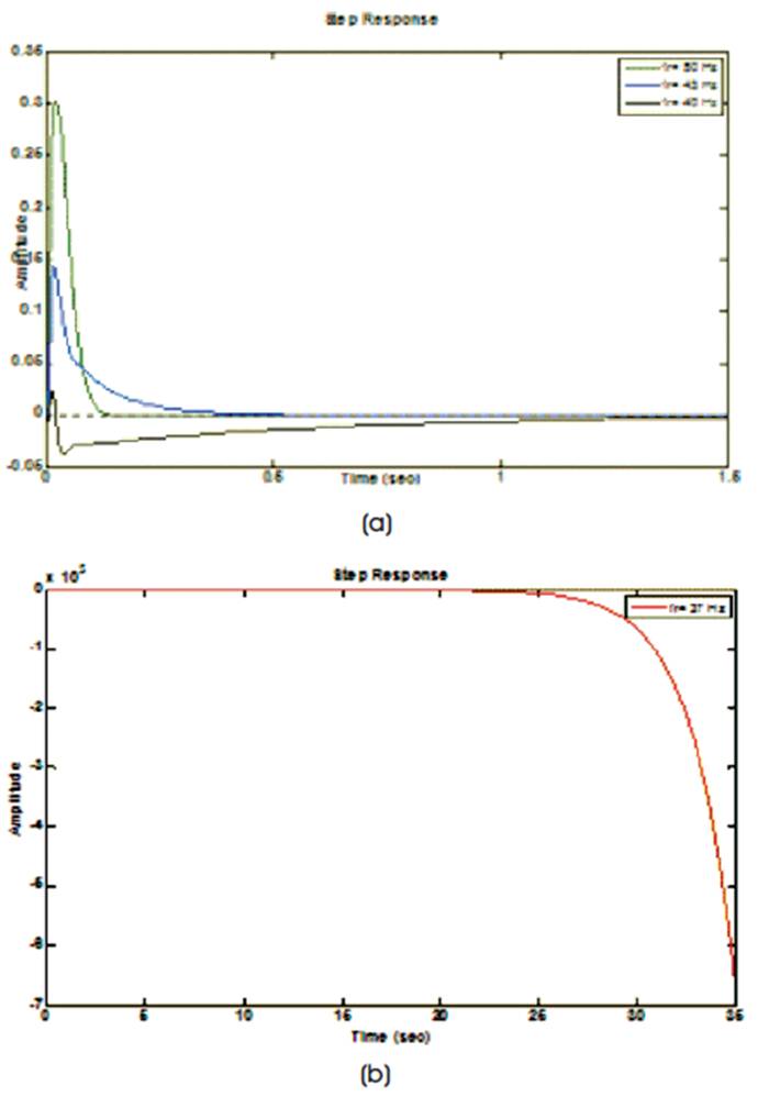
Figure 1. Step Response
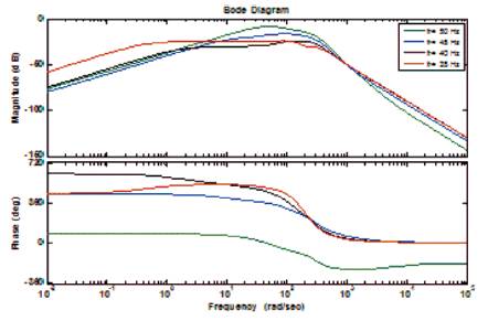
Figure 2. Bode Diagram
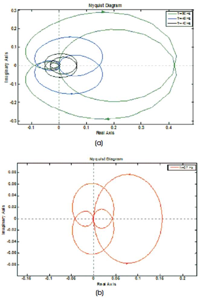
Figure 3. Nyquist Diagram
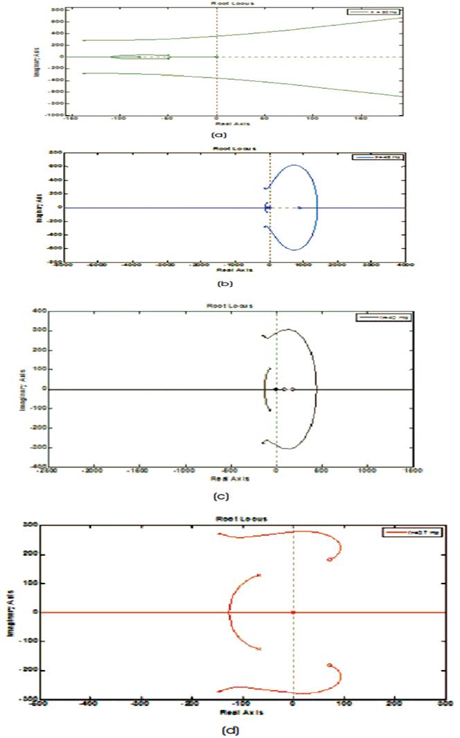
Figure 4. Root Locus Diagram
So it has been concluded that when transfer function technique for the stability analysis is carried out using different stability criteria, the three phase induction motor drive reaches to unstable operation at a rotor frequency of 37 Hz.
In this paper discussion on the stability analysis of three phase induction motor drive is done using variable frequency method. Linearization of the model is made and the state space form of the induction motor drive is obtained. This linearized model is then used to determine the transfer function which helps in the determination of stability of the induction motor drive by varying the rotor frequency (and hence rotor speed). Different stability criteria of control system such as Root-locus, Bode plot, Nyquist plot have been used to determine the stability analysis of three-phase induction motor drive system. The behavior the motor drive for different frequency (and hence rotor speed) is studied using Matlab codes.
The rotor frequency is varied from no load, i.e. 50 Hz (rotor speed 314 rad/sec) to 37 Hz (rotor speed 233 rad/sec) and the behavior of the motor drive is observed. The threephase induction motor drive behaves stably at all the frequencies higher than 37 Hz. So the three-phase Induction Motor Drive is unstable at a frequency of 37 Hz. The results obtained by this technique is based on the voltage-flux linkage model.
A - State transition matrix
B - Control Matrix
C - Observation Matrix
D - Direct Transmission Matrix
th D - i column vector of D-matrix
f - friction coefficient
f - Stator supply frequency (Hz)
f - Rotor supply frequency (Hz)
I I - d & q - axis stator current, Amp.
I , I - d & q - axis rotor current, Amp.
I , I - stator current in x and y axis, Amp.
I , I - rotor current in x and y axis, Amp.
I , I - stator and rotor zero sequence current, Amp.
2 J - total moment of Inertia, kg-m
L - magnetizing inductance per phase, H
L - Magnetizing inductance per phase in q-d axis, H
L - Magnetizing inductance per phase in x-y axis, H
L - Stator inductance per phase, H
L - Rotor inductance, H
L - stator referred rotor leakage inductance /phase, H
L - stator leakage inductance per phase, H
P - number of poles
p - d/dt, differential with respect to time
R - stator resistance per phase, Ohm
R - stator referred rotor - phase resistance, Ohm
T - electro magnetic torque (N-m)
T - shaft torque (N-m)
T - Load torque (N-m)
V , V - d & q -axis voltage of stator, Volts
V , V - d & q -axis voltage referred to stator, Volts
y, y- d & q –axis rotor flux linkage, V-s
y, y- d & q –axis stator flux linkage, V-s
y, y- stator flux linkages in x-y axis, V-s
y, y- rotor flux linkages in x-y axis, V-s
y- zero sequence flux linkage of stator, V-s
y- zero sequence flux linkage of rotor, V-s
X - state variable vector
Rating and parameters of the three-phase Induction Motor Drive.
Three Phase, 220 Volts, 50 Hz, 4-Pole,
R = 10 Ohm
R = 6.3 Ohm,
L = 0.46 H,
L = 0.46 H,
L = 0.42 H,
2 J = 0.03 kg-m ,
B = 0.0 ms/rad.