[1]
This paper investigated Load Frequency Control (LFC) using an Artificial Intelligence (AI) technique called Adaptive Neuro-Fuzzy Inference System (ANFIS). ANFIS controller is simple to apply and at the same time it can handle system nonlinearities very effectively. ANFIS controller gives better dynamic response and it is faster than proposed controllers. Dynamic analysis was done without controller, with Proportional Integral Derivative controller (PID controller), Fuzzy controller, Linear Quadratic Regulator (LQR), and with Adaptive Neuro-Fuzzy Inference System (ANFIS) controller using Matlab/Simulink. The results of ANFIS controller was compared with results obtained from other controllers and it is observed that it has improved system performance in terms of steady state response and reduced oscillations and at the same time it is faster than above proposed controllers.
Nowadays the electrical power system is being interconnected, if a power load demand varies randomly, then both area frequency and tie-line power interchange also vary. The main objective of load frequency control of interconnected power system [5] is to maintain desired power frequency and to regulate the power interchange [3], [7], [10] with surrounding systems. If there is any difference between generation and demand then there will be deviation in system frequency from its nominal value. Because of this high frequency deviation the system may collapse. This creates need for a very fast and accurate controller to maintain the nominal system frequency.
Adaptive Neuro-Fuzzy Inference System (ANFIS) is a controller which has neural network based on fuzzy inference system. Artificial Neural Network, provides good steady state response but settling time is more. ANN requires training and it takes a lot of time for processing mainly in case of large neural networks. To overcome these type of difficulties, ANFIS is used. It has the potential to capture the benefits of both fuzzy and neural networks. ANFIS controller has high learning capability to approximate nonlinear functions.
Adaptive Neuro-Fuzzy inference System is taking benefits of both Artificial Neural Network and Fuzzy Inference Systems. ANFIS is having a neural network which is trained by inference system containing set of fuzzy IF_THEN rules. The main purpose of the ANFIS controller is to automatically tune the fuzzy system by using the neural network methods. ANFIS authorizes both the combinational and linguistic data. In addition to that, Neuro-Fuzzy systems have the ability to obtain fuzzy information from its numerical data. Thus ANFIS is getting results from fusion of neural networks and fuzzy logic.
The methodology of this paper includes starting from the basic of the load frequency control of a two area power system without any controller, then with PI controller, conventional PID controller, fuzzy controller, LQR controller, ANFIS controller when disturbance is applied to it. A number of control techniques have been used in this investigation, to evaluate the better dynamic per formance characteristics for the taken system. Finally, by observing all the results obtained from these proposed controllers, took the best controller is chosen based on performance measures, such as settling time, and peak overshoot.
A two area power system (thermal-thermal) has been considered, in which each area is assumed to have one equivalent generator and is equipped with governorturbine system [5]. The control signals are being connected to the controllers. The plant chosen is a non-reheated turbine [7], [13], [14] that consists of mainly three parts.
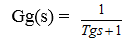
Governor with dynamics is given by,
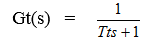
Turbine with dynamics is given by,
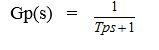
Load and machine with dynamics is given by,
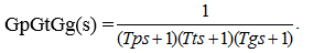
Then the open-loop transfer function without droop characteristic for load frequency control is,
The grouping of all the above basic blocks in addition to the controller which we want to use is placed as shown the block diagram [1], [10], [14] of two area power system. Figure 1 gives the block diagram for two area thermal power system.
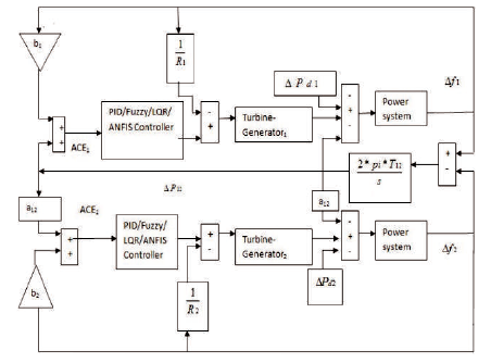
Figure 1. Block Diagram for Load Frequency Control Two area Power System
The conventional Integral controllers are very slow in operation, and at the same time an integral controller is known as a fixed type of controller [9]. It is optimal in one condition but at another operating point of system it is unsuitable. We can overcome this drawback by PID controller. The block diagram of PID controller is given in Figure 2 which has three main blocks proportional (P), integral (I), and derivative (D).
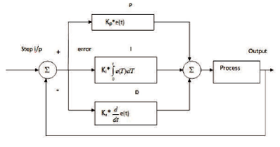
Figure 2. Block Diagram of a PID Controller
PID controller for a two area non reheat thermal power system can be simulated by using Matlab/Simulink as shown in Figure 3.
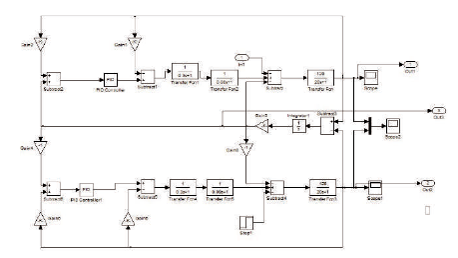
Figure 3. Simulink Diagram of Two Area Power System with PID Controller
For the simulation figure of two area load frequency thermal-thermal power system with PID controller, the step load disturbance was applied to area 2, then the corresponding change in frequencies in area 1 and area 2 are obtained as in Figure 4.
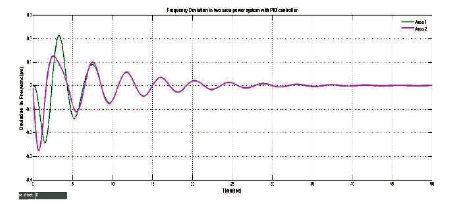
Figure 4. Frequency Response of Two Area Power System with PID Controller
The frequency of each area under disturbances was observed by using Matlab/Simulink. It has settling time of 50 seconds, 55 seconds in area 1, area 2, respectively, and steady-state error was also reduced to zero, less peak overshoot. But the system response is more oscillatory. To improve frequency response further and to reduce oscillations, artificial intelligent techniques are used.
The Fuzzy Logic Controller (FLC) has block diagram given in Figure 5, has a structure that consists of four components.
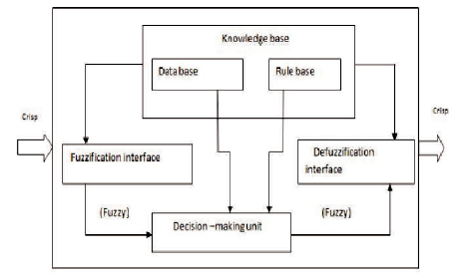
Figure 5. Structure of Fuzzy Logic Controller
Fuzzification [11] will transform the crisp control input values of the controller to fuzzy domain [12]. Selection of fuzzy system control variables [8], [13] will depend on the nature of the system selected and its desired output. Seven linguistic variables were used in this process for each of the input variable to get the required performance; the linguistic variables were given by a Gaussian membership functions as shown in Figures 6, and 7. Membership functions measures the fuzziness of a control variable. A set of membership used for seven linguistic variables were NB (Negative Big), NM (Negative Medium), NS (Negative Small), ZE (Zero), PS (Positive Small), PM (Positive Medium), PB (Positive Big) respectively.
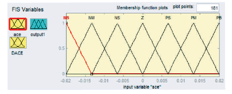
Figure 6. Membeship Function for Area Control Error
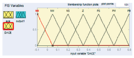
Figure 7. Membership Function for Change in Area Control Error
The fuzzy systems always map input fuzzy sets to output fuzzy sets [12]. The modes of deriving fuzzy rules [8], [11] were almost based on trial and error method. Since each of the input variables contains seven linguistic variables, as a result total 49 rules were devised. The fuzzy rules are given by Table 1.
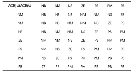
Table 1. Fuzzy Inference Rules
The following is the simulink model of two area load frequency control with fuzzy logic controller.
For the Simulink model given in Figure 8, step load disturbance was applied to area 2 and the simulation results were obtained as in Figure 9, and Figure 10.
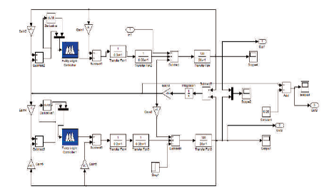
Figure 8. Simulink Model of Two Area Load Frequency Fuzzy Logic Controller
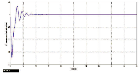
Figure 9. Frequency Deviation in Area 1 with Fuzzy logic Controller
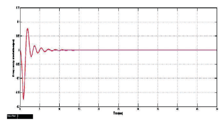
Figure 10. Frequency Deviation in Area 2 with Fuzzy Logic Controller
The simulation model shows that the two area system is simulated with the Fuzzy logic control [4], [6] and the response obtained was better than previous PID control, i.e., the settling time is reduced from 55 seconds to 14 seconds in area 1, whereas in area 2 it is reduced from 50 seconds to 14 seconds. The responses are shown in Figure 11 and Figure 12, respectively.
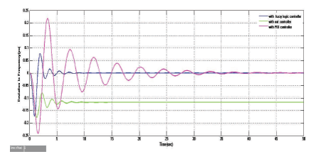
Figure 11. Comparison of Fuzzy Controller with PID Controller and without Controller in Area 1
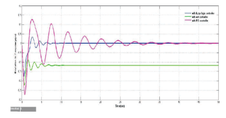
Figure 12. Comparison of Fuzzy Controller with PID Controller and without Controller in Area 2
To improve system frequency further and reduce settling time, peak overshoot and oscillations Linear Quadratic Regulator is applied to the two area power system.
Linear Quadratic Regulator (LQR), which is an optimal controller and a very well known controller due to its wide area use. It was so called linear is that, it is applicable to linear systems. Quadratic means it has a quadratic objective function, which is to be minimised. Load frequency control of two area power system is basically a non linear system. So for the application of Linear Quadratic Regulator to the system, it should be linearized about a single operating point. A state space model [9] is found out which was the linearized form of the non linear system, for Linear Quadratic Regulator [1] to be applied.
LQR is a feedback controller; it is also an important part of solution to the Linear-Quadratic-Gaussian problem [1], [7]. The block diagram for two area non reheat thermal power system is given in Figure 13.
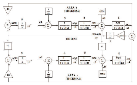
Figure 13. Block Diagram for the Two Area Thermal-Thermal Power System
The states of automatic load frequency control system (ALFC) are as below,
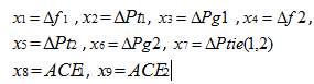
LQR take inputs which are linear combinations of specified inputs x1, x2, x3, x4, x5, x6, x7, x8, x9 which are taken as control input u given by equation (5)
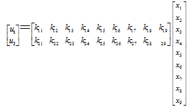
where k (2×9) is feedback Gain matrix.
The state equation of the system is given in equation (6).

where A, B are given by,

The step load change for a constant magnitude is zero
The equation of output is,

Since D was assumed to be zero.
The feedback gain matrix k can be found based on performance index PI which is given as,

Here Q, R are given by,

The matrices A, B, Q, R can be found out and the optimal control law is given by u=-kx.

where s can be given by Riccati equation given as,

After solving s we can get k from equation (9). From this analysis, we can calculate feedback gain matrix k and finally simulate LQR using these values of matrices A, B, Q, R, k. The simulated LQR is as shown in Figure 14. The k matrix can be easily found using Matlab command [k, s] = lqr (A, B, Q, R).
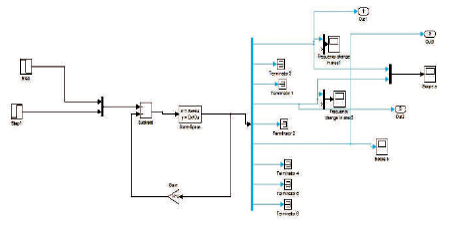
Figure 14. Simulation Diagram of LQR
After simulating LQR, the frequency deviation in area 1, area 2 are obtained as shown in Figure15.
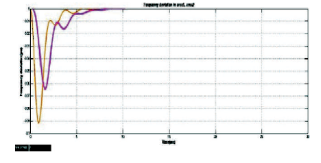
Figure 15. Frequency Deviation in Area 1 and Area 2 with LQR
LQR controller is compared with PID, fuzzy controller in area 1 and area 2, which are given by Figure 16 and Figure17, respectively.
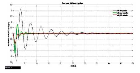
Figure 16. Comparison of LQR with PID, Fuzzy, Controller in Area 1
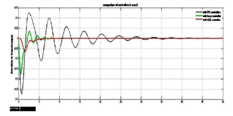
Figure 17. Comparison of LQR with PID, Fuzzy, Controller in Area 2
From the results of LQR it is observed that the optimal regulator (LQR) [1], [7] is not sufficient for full state feedback and also is not applicable at noisy environments. So in order to achieve the system performance nearer to its optimum it is desirable to track the operating conditions of the system at different conditions and finally we have to use updated parameters for better control. Adaptive neuro fuzzy inference system controllers with self adjusting gains settings have been proposed for LFC to achieve better
Adaptive Neuro Fuzzy Inference System (ANFIS) [11] was a kind of neural network which is based on the fuzzy inference system. Its inference system corresponds to a set of fuzzy IFTHEN rules. In ANFIS controller based system [16], fuzzy sugeno models were involved in framework of adaptive system to facilitate the learning and adaption studies. Moreover, Neuro-Fuzzy systems have the ability to obtain fuzzy information from the numerical data. In the adaptive neuro-fuzzy model, two basic learning algorithms were required. One of them is the structural learning algorithm which is used to find suitable fuzzy logic rules [12], [17] and second one is the parameter learning algorithm which is used to adjust the membership functions and other parameters according to desired performance from the system. For this cause, the approach is generally expressed as Neuro-Fuzzy modelling. ANFIS results have been obtained from fusion of neural networks and fuzzy logic [11]. A fuzzy logic controller [8] is used provide the required training data. There are two inputs to the controller they are ACE and rate of change of ACE and the output is the control signal. The ANFIS was a multi layer Adaptive neural network is based an fuzzy inference system. ANFIS algorithm is composed of fuzzy logic and neural network to implement different node functions and tune parameters of Fuzzy Inference System (FIS) structure. The development of the control strategy to control the frequency deviation of the two area power system using the concept of ANFIS control scheme is presented here. The Neuro-fuzzy method mixes the advantages of both neural networks and fuzzy theory to design a model which uses a fuzzy theory to represent knowledge in an interpretable manner and the learning ability of a neural network to optimize its parameters. The simulation block diagram for ANFIS based load frequency control for a two area non reheat thermal power system is as shown in Figure 18. It consists of both fuzzy controller, neural network, and the subsystem used in this figure is a two area non reheat thermal power system.
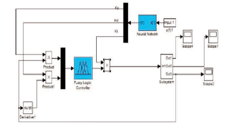
Figure18. Simulink Model of ANFIS Controller
From the simulation Figure 18, the step load disturbance is applied to area 2 then the frequency deviation in area 1 and area 2 are as in Figure 19 and Figure 20, respectively.
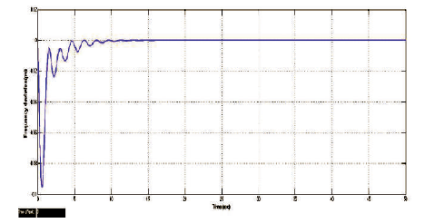
Figure 19. Frequency Deviation with ANFIS Based Controller in Area 1
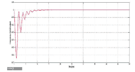
Figure 20. Frequency Deviation with ANFIS Based Controller in Area 2
Figure 21 gives the comparison of load frequency control of two area power system with PID, Fuzzy, LQR, and ANFIS. Finally the results are obtained as in Figures 21, 22, and 23.
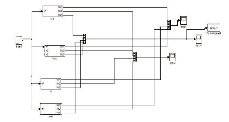
Figure 21. Simulink Block Diagram for Comparison of Different Controllers
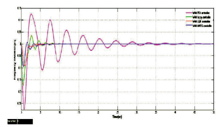
Figure 22. Comparison of ANFIS with PID, Fuzzy, LQR Controller Frequency Change in Area 1
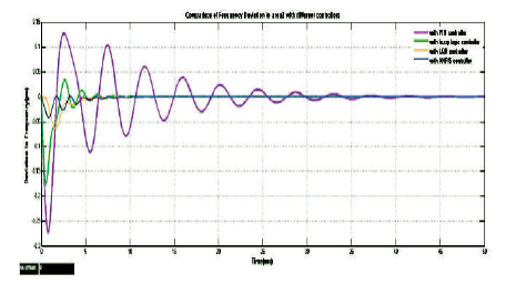
Figure 23. Comparison of ANFIS with PID, Fuzzy, LQR, Controller in Area 2
From the comparison in Table 2, it is clearly noticed that the Adaptive Neuro Fuzzy Inference System based Load frequency Controller [15], [16] gives best control action compared to PID and Fuzzy Controllers [15]. Following are the key observations made. ANFIS Controller is simple for implementation and it is suitable for adjustable gain parameters than the LQR. The proposed Adaptive Neuro Fuzzy Inference controller can handle the nonlinearities [2], [16] quickly when compared to PID, Fuzzy Controller and bring steady state deviation in frequency to zero.
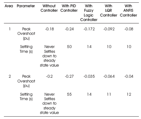
Table 2. Comparison of Results
In this paper, the Adaptive Neuro Fuzzy Inference System (ANFIS) based controller has been proposed for Load Frequency Control of a two area non reheat thermal power system. The results have been compared with PID, Fuzzy, and LQR controller. The results have proved that the Adaptive Neuro Fuzzy Inference System based load frequency control gives better response compared to the different controllers PI, PID, fuzzy, LQR in terms of peak overshoot and settling time. Even though LQR also gives better results, but that the optimal regulator (LQR) is not sufficient for full state feedback and also is not applicable for noisy environments. Most for the state feedback controllers based on linear optimal control theory has been proposed to achieve better performance, at the same time fixed gain controllers [1] were designed at nominal operating conditions and they fail to provide best control performance. Finally about ANFIS controller we can say that, it is simple to design and easy to implement. The proposed ANFIS controller becomes more effective because to its ability of adapt to disturbances.