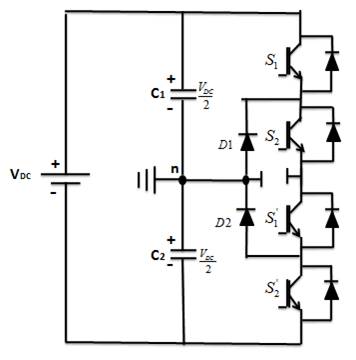
Figure 1. A Basic Three Level Configuration of NPDCMLI
Multilevel inverters are popular in high voltage applications and have become an important concept of research. The design and operation of these inverters are getting simpler and attaining improvement due to the advances in power semi conductor devices and modulation techniques. Multilevel inverters are known for their ability to produce a synthesized AC output voltage with negligible harmonic distortion. This paper compares three different topologies on Multilevel inverters- Neural Point- Diode Clamped Multilevel Inverter, Flying Capacitor Multilevel Inverter, and Cascaded H-Bridge Multilevel Inverter. The performances of inverters are compared in terms of number of IGBT switches, capacitors, diodes, DC voltage sources required for each configuration and harmonic distortion in output voltage. All the inverters are designed and simulated on MATLAB / SIMULINK platform and the results are presented.
Switch Mode DC-to-AC inverters are employed in AC Power supplies and AC Motor Drives, where the objective is to produce a sinusoidal AC output whose magnitude and frequency can both be controlled. Practically, an inverter is used in both single-phase and three phase AC systems. A Half-Bridge Inverter is the simplest topology, which is used to produce a two level square-wave output waveform. A centre-tapped voltage source is needed for such topology. It may be possible to use a simple supply with two well-matched capacitors in series to provide the centre tap. Today, Multilevel Inverters are extensively used in highpower applications with medium voltage levels. Applications of multilevel inverters, include laminators, mills, conveyors, pumps, fans, blowers, compressors, and so on. Recent advances in the power-handling capabilities of static switch devices such as IGBTs, made the use of the Voltage Source Inverters (VSI) feasible for high-power applications [2]. High power and high-voltage conversion systems have gained focus and became important topics of research in the power electronic industry, handling large AC drive and electrical power applications at both the transmission and distribution levels. For these reasons, a new family of Multilevel Inverters has emerged as the solution for working with higher voltage levels. Multilevel Inverters include an array of power semiconductors and capacitor voltage sources, the output of which generates voltages that are usually stepped waveforms [3, 4]. Capacitors, batteries, and renewable energy voltage sources can be used as the multiple DC voltage sources for Multilevel inverters. The commutation of the power switches aggregates these multiple DC sources in order to achieve high voltage at the output [5].
An inverter is a device that converts DC input power to AC output power at desired range and frequency. The term multilevel starts with the Three-Level Inverter introduced by Nabae et al. [1]. By increasing the number of levels in the inverter, a staircase output voltage is generated, which reduces harmonic distortion. However, the higher number of levels increases the control complexity, complications in design, and introduces voltage imbalance problems [6] . A multilevel converter that uses high switching frequency Pulse Width Modulation (PWM) has several advantages over a conventional Two-Level Converter. The attractive features of a multilevel converter can be briefly summarized as follows.
An inverter is a device that converts DC input power to AC output power at desired range and frequency. A multilevel converter that uses high switching frequency Pulse Width Modulation (PWM) has several advantages over a conventional Two-Level Converter. The attractive features of a multilevel converter can be briefly summarized as follows [7, 8].
Multilevel converters not only generate the output voltages with very low distortion, but also reduce the dv/dt stresses; therefore electromagnetic compatibility (EMC) problems are reduced.
Multilevel converters produce smaller CM voltage; therefore, the stress in the bearings of a motor connected to a multilevel motor drive can be reduced. Furthermore, CM voltage can be eliminated by using advanced modulation strategies.
Multilevel converters can draw input current with low distortion.
Multilevel converters can operate at both fundamental switching frequency and high switching frequency PWM. It should be noted that the lower switching frequency is usually associated with lower switching loss and higher efficiency.
Apart from several advantages, multilevel inverters also have some disadvantages. The need for number of power semiconductor devices increases with two factors, one is the number of output voltage levels and other factor is the type of multilevel converter configuration. Although lower voltage rated switches can be utilized in a multilevel converter, each switch requires a separate gate drive circuit. This causes the overall system to be more expensive and complex.
Different types of multilevel converter topologies were proposed during the last two decades. Contemporary research has engaged novel converter topologies and unique modulation schemes. Moreover, three common multilevel converter structures reported in the literature are Cascaded H-Bridge Converter with separate DC Sources, Diode Clamped (Neutral-Clamped), and Flying Capacitor (Capacitor Clamped) converters. Also, abundant modulation techniques and control paradigms have been developed for multilevel converters, such as Sinusoidal Pulse Width Modulation (SPWM), Selective Harmonic Elimination Pulse Width Modulation (SHE-PWM), Space Vector Pulse Width Modulation (SVPWM), etc. In addition, many multilevel converter applications focus on industrial medium-voltage motor drives, utility interface for renewable energy systems, Flexible AC Transmission System (FACTS), and traction drive systems. This paper discusses the analysis and operation of different Five level inverters and compared in terms of output voltage, number of switches required, and level of harmonic distortion in the output voltage waveform.
Diode Clamped Multilevel Inverter was proposed by Nabae, Takashi, and Akagi and was first patented in the year 1975 [1]. This three level inverter was basically named as Neutral Point Diode Clamped Inverter. The converter consists of two pairs of series connected switches, upper and lower pairs connected in parallel with series capacitors as shown in Figure 1. The anode of the upper diode (D ) is 1 connected to the midpoint (neutral) of the capacitors and its cathode to the midpoint of the upper pair of switches (S 1 and S ). The cathode of the lower diode (D ) is connected to 2 2 the midpoint of the capacitors and divides the main DC voltage into smaller voltages, as shown in Figure 1. The middle point of the two capacitors can be defined as the “neutral point”. The Neutral Point Clamped converter uses a single DC bus that subdivides the input voltage into a number of lower voltage levels by means of a series string of capacitors [9].
Figure 1. A Basic Three Level Configuration of NPDCMLI
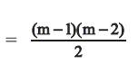
If 'm' represents, the number of output voltage levels, then, the number of capacitors required on DC bus is given by,
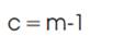
The number of switches in each leg is given by,
For a five level NPDCMLI, for output voltage levels m=5, the number of capacitors required on DC bus is 4.
The number of switches required in each leg is 8.
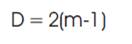
Figure 2 shows Five Level Configuration of NPDCMLI.
The switching states of Five level NPDCMLI are given in Table 1.
Figure 2. Five Level Configuration of NPDCMLI
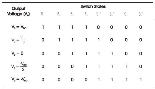
Table 1. Switching States of Five Level Neutral Point Diode Clamped Inverter
It can be incurred from the Table 1 that for achieving an output voltage of V , all the upper switches (S , S , S , S ) must be turned ON. For obtaining output voltage of V /2, DC any three of the upper switches and any one of the lower switches must be turned on. For obtaining output voltage of -V /2, any three of the lower switches and any one of the DC upper switches must be turned ON. For achieving output voltage of V , all the lower switches must be turned on.
The merits of NPDCMLI include a large number of output voltage levels with minimum harmonic distortion, requirement of a common DC bus for all the three phases and simple in operation [10, 11]. The demerits include requirement of different voltage rated clamping diodes and voltage imbalances between the capacitors of DC bus.
This inverter is similar to NPDCMLI except that the diodes in NPDCMLI are replaced with the capacitors as shown in Figure 3. FCMLI also known as Capacitor Clamped Inverter was proposed and developed by Hochgraf et al (1994) and Lai et al (1996). The size of the voltage increment between two capacitors determines the size of the voltage levels in the output waveform. Due to the redundancy in the switching states, the capacitor voltages can be regulated such that the desired output voltage can be obtained.
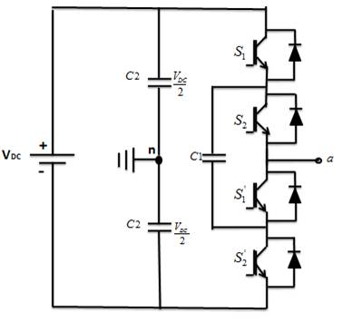
Figure 3. A Basic Three Level Configuration of FCMLI
Figure 3 shows a Three level FCMLI. The output voltages that can be generated are . The output voltage is obtained when the upper switches S and S are turned on. 1 2 For achieving ‘0’ output voltage, the switch pairs, S , S ’, or S , 1 1 2 S ’ can be turned ON. The output voltage is obtained 2 when the lower switches S ’ and S ’ are turned ON.
For an 'm' level inverter,
Number of balancing capacitors
Number of switching devices =

Thus for a Five level FCMLI, for m=5,
Number of balancing capacitors required is 6.
Number of switching devices required is 8.
Number of capacitors required in DC link is 4.
Figure 4 shows Five Level Configuration of FCMLI.
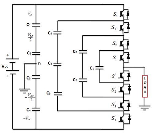
Figure 4. Five Level Configuration of FCMLI
The switching states of Five Level Flying- Capacitor Inverter is given in Table 2. For achieving output voltage V = V , all 0 DC the upper switches S , S , S , S are turned ON. For achieving 1 2 3 4 , three upper switches and one lower switch must be turned ON. For achieving V = 0, two upper switches and 0 two lower switches must be turned ON. For achieving , three lower switches and one upper switch must be turned ON. For achieving V = -V , all the four lower 0 DC switches must be turned ON.
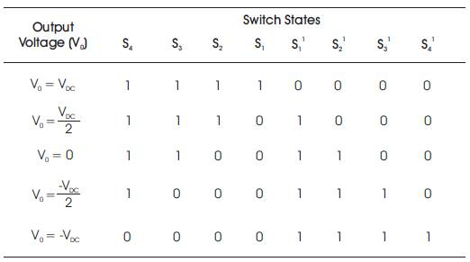
Table 2. Switching States of Five Level Flying- Capacitor Inverter
Merits of FCMLI include low harmonic distortion as the number of output levels increase and controlled active and reactive power flow. Some of the disadvantages of FCMLI are high cost due to the large number of capacitors, complexity in maintaining the voltage balance of the capacitors, and poor efficiency for real power transmission.
Cascaded H-Bridge Multilevel Inverter is an alternative for the above discussed Multi level inverters. This configuration is based on series connected H-Bridges with separate DC sources. For multilevel configuration, H-Bridges are connected in series, which requires the DC sources to be isolated from each other. For higher voltage levels, fuel cells and Photovoltaic arrays can be used instead of DC sources. Figure 5 shows a basic H-Bridge circuit which results in three levels of output voltages V , 0, -V .
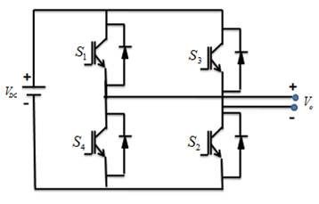
Figure 5. A Basic Three Level Configuration of CHB-MLI
For obtaining output voltage V = V switches S and S 0 DC 1 2 must be turned ON. For obtaining output voltage V = 0, 0 either of the switch pair (S , S ) or (S , S ) must be turned ON. 1 3 2 3 For obtaining output voltage V = -V , switches S and S 0 DC 3 4 must be turned ON.
Figure 6 shows a Single-phase, Five-Level Cascaded HBridge cell realized by connecting two three level conventional Full Bridge inverters. In general, if 'm' is the number of output voltage levels, then the number of DC voltage sources required (or the number of H-Bridges required, 's' is given by,
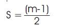
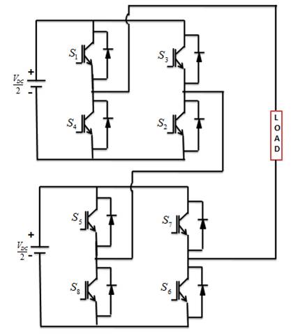
Figure 6. Five Level Configuration of CHB-MLI
Thus for a Five level Cascaded H-Bridge Inverter, 2 DC sources are required for each phase.
Switching states for the Five level CHB-MLI is given in Table 3.
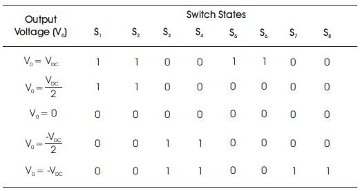
Table 3. Switching States of Five Level Cascaded H- Bridge Inverter
The five levels of output voltages obtained are . For obtaining output voltage of V switches S , S , S , S must be turned ON. For DC 1 2 5 6 obtaining output voltage of , switches S and S must be 1 2 turned ON and S , S must be turned OFF. For obtaining 3 4 output voltage of , switches S and S must be turned 3 4 ON and S , S must be turned off. For obtaining output 1 2 voltage of -V switches S , S , S , S must be turned ON.
Cascaded H-Bridge Multilevel Inverters have a modularized structure. Clamping diodes are not necessary and necessity of voltage balancing is avoided due to absence of capacitors. However, this type of topology requires separate DC sources.
Figure 7 shows the Simulink block diagram of Five Level Neutral Point Diode Clamped Inverter. The output voltage waveform of the inverter is shown in Figure 8 and its corresponding harmonic spectrum is shown in Figure 9 and is about 20.33%.
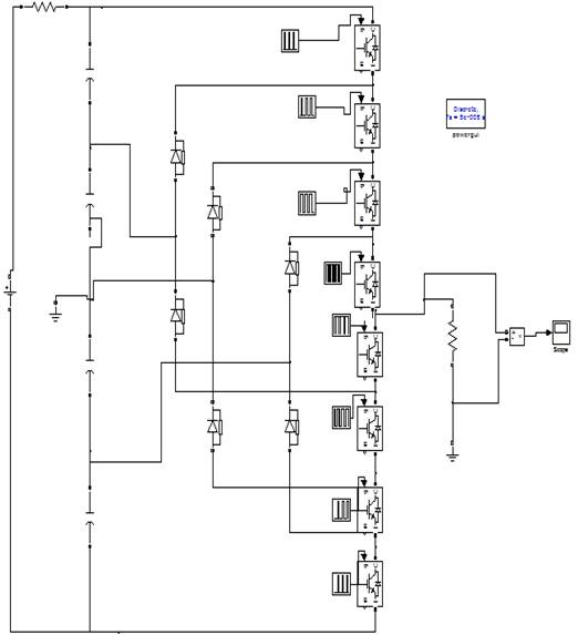
Figure 7. Matlab / Simulink Model of Five Level Neutral Point Diode Clamped Inverter
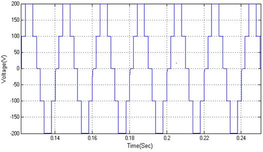
Figure 8. Output Voltage Waveform obtained From Five Level Neutral Point Diode Clamped Inverter

Figure 9. FFT Analysis of Neutral Point Diode Clamped Inverter
Figure10 shows the Simulink block diagram of Five Level Flying Capacitor Inverter. The output voltage waveform of the inverter is shown in Figure 11 and its corresponding harmonic spectrum is shown in Figure 12 and is about 20.33%.
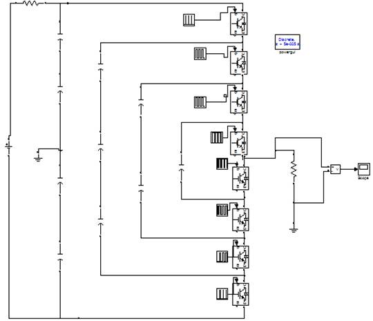
Figure 10. Matlab / Simulation Model of Five Level Flying Capacitor Inverter
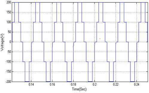
Figure 11. Output Voltage Waveform Obtained from Five Level Flying Capacitor Inverter
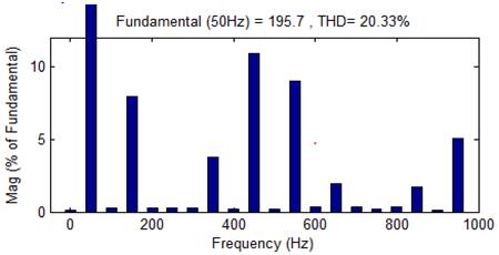
Figure 12. FFT Analysis of Five Level Flying- Capacitor Inverter
Figure 13 shows the Simulink block diagram of Five Level Cascaded H- Bridge Inverter. The output voltage waveform of the inverter is shown in Figure 14 and its corresponding harmonic spectrum is shown in Figure 15 and is about 20.49%.
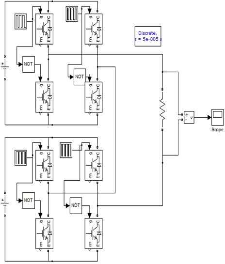
Figure 13. Matlab / Simulation model of Five Level Cascaded H-Bridge Inverter
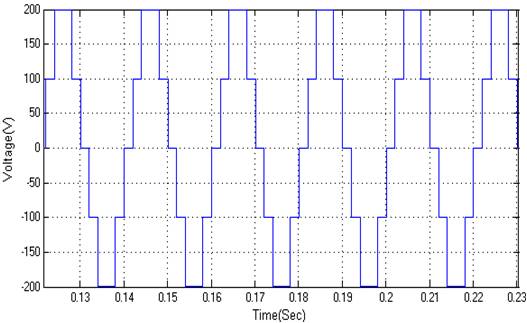
Figure 14. Output Voltage Waveform Obtained from Five Level Cascaded H-Bridge Inverter
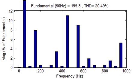
Figure 15. FFT Analysis of Five Level Cascaded H- Bridge Inverter
The number of power components as required by multilevel topologies for each phase is mentioned in Table 4. NPDCMLI topology requires 6 diodes for each phase. FCMLI and CHB-MLI topologies do not need any diodes. The number of capacitors as required by FCMLI topology is 10 for each phase. NPDCMLI topology requires 4 capacitors, whereas CHB-MLI topology needs no capacitors. Also, NPDCMLI and FCMLI topologies require only one DC source for each phase, where CHB-MLI topology requires two DC voltage sources.
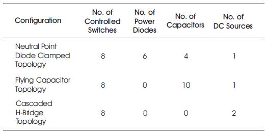
Table 4. Comparison of Power Components requirement for Each Phase of the Inverters
Table 5 gives the details, of amount of harmonic distortion present in each phase of the output voltages of inverter topologies. As per the details, the percentage of harmonic distortion is nearly equal for all the inverter topologies.
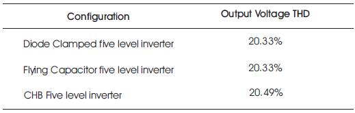
Table 5. Percentage THD Comparision of Output Voltage
It can be observed from the analysis that in order to obtain the same five level output voltage, the three different topologies require different number of power components. The total number of power components required for Diode Clamped Configuration and Flying Capacitor configuration is high as compared to Cascaded H- Bridge configurations. The number of IGBT switches required remains equal for all topologies. The number of capacitors required for Flying Capacitor configuration are high due to which voltage balancing of capacitors becomes a complication. Cascaded H-Bridge topology requires many number of DC voltage sources. However, this inverter is quite simple in structure and easy to control.