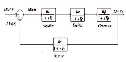
Figure 1. Linear Block Diagram of an AVR System
In the last few decades, in all types of industries, approximately the most common types of controllers are PID controllers. They have found a huge acceptance and application in distinct industry. The most common types of controller used in process control are PID controllers due to their efficient response. Proper tuning rules are required for PID controller to give desired output and appropriate performance. There are progressive researches going on, to develop novel methods for PID tuning rules and designing. A large number of algorithms have been grown up by researchers and appropriate methods according to the application are approved by industries for PID tuning and designing. The authors aim to find out the way, which provides better tuning parameterization and better response. In this paper, the superiority of FOPID controller over conventional PID controller is discussed using MATLAB/SIMULINK. In recent years, FOPID controllers replaced all the PID controllers in many areas of engineering and science. The concept of FOPID controller was first invented by Podlubny in 1997.
Every industry requires a good regulation and a constant voltage level for their dynamics [1]. So the automatic voltage regulator[12] is a tool or machine which is broadly used in industrial application to get the stability and good regulation of various electrical equipments [2]. A voltage regulator [17] is an electrical machine designed to automatically maintain a constant and desired voltage level. According to the design, it may be adopted to regulate one or more than one AC or DC voltages [5]. If the output voltage is very small, the regulation part is directed up to a point to generate a higher output voltage from dropping a few of the input voltage. If the output voltage is very high, then it will normally be directed to generate a lower voltage. Along with the development of renewable sources[7], it has become necessary to try and interface these sources to the actual power system that is delivered from the main generation. The complete system is the hybridization of a simple AVR [12, 13] and a speed governing system. Due to the simplicity of design and better response to have a low percentage of overshoot and low settling time, the PID[4] controllers are mostly used in industries for process control. The performance of PID [3] controller is further modified by setting of FOPID [20, 21] controllers. This paper aims to study the response of Fractional order PID controller over Integer order PID controllers. After the establishment of FOPID [18] controllers, besides setting the P, D, and Integral constant Kp , KD , and Kl respectively, we have two additional parameters in FOPID[18] controllers given as power of “s” in integral and in derivative terms “λ” and “μ”, respectively. The automatic voltage regulator system [8, 9] is a closed loop control system, which gives a terminal voltage at the desired level[22]. The AVR handles the terminal voltage by maintaining the exciter voltage of the generator [10]. .
This paper shows the comparative visualization of Integer Order PID and Fractional Order PID controller output for AVR system. The FOPID[11, 18] controllers have best parameters, namely, the proportional gain Kp , integral gain Kl , fractional order of Integrator λ , derivative gain KD , and fractional order of differentiator μ for the AVR system to give a better control performance than others [14,15].
To maintain a constant voltage level in any power system, the most important factor is excitation control of synchronous alternator. The function of AVR [12] is to maintain the terminal voltage magnitude of a synchronous generator at a nominal value. Figure 1 shows the linear block diagram of an AVR system. A simple AVR system [13] constitutes four main elements, namely amplifier, exciter, generator, and sensor. The end voltage of a synchronous generator is steadily sensed by a voltage sensor which is further rectified, smoothened and compared with a reference signal. The error voltage from the comparator is amplified and utilized to control the excitation winding of the generator. When the generator is driven (at frequency 50 Hz with a constant output voltage magnitude), it will be revolving at a relatively constant speed. While the spinning of generator is affected by the load, when the load increases the speed of the generator will drop and the opposite will also be true for this. The transfer function and parameter range of AVR is shown in Table 1.
Figure 1. Linear Block Diagram of an AVR System
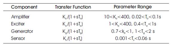
Table 1. Parameters Limit for AVR
Transfer function of AVR's amplifier is,
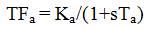
where, Ta and Ka are the time constant and gain of the amplifier system, respectively.
Transfer function of AVR's exciter is,
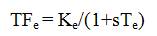
where, Te and Ke are the time constant and gain of the exciter system, respectively.
Transfer function of AVR's generator is,
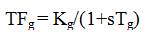
where, Tg and Kg are the time constant and gain of the generator system, respectively and dependent on the load.
Transfer function of AVR's sensor is ,
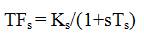
where, Ts and Ks are the time constant and gain of the sensor system, respectively.
There are various types of controllers being developed in process control of engineering and science which requires proper modeling and tuning methods. Integer order PID controller comprises three basic types of controller which are P (Proportional), I (Integral), and D (Derivative). The response of AVR without controller is shown in Figure 2.
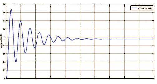
Figure 2. Response of AVR without Controller
The PID controller[4] is most popular and widely used due to their robustness and excellent control performance in contempt of different dynamic characteristics of process plant. The PID controller for closed system shown in Figure 3. As the name signifies, the PID algorithm comprises three basic modes, proportional mode, integral mode, and derivative mode. A proportional mode is responsible for reducing the rise time, but never deals with the steady state error. In case the proportional gain is too high, the system may become unstable while a small gain causes a small output response to a high input error. An integral controller is responsible for removing the steady state error, but it may cause the transient response atrocious. High integral gain may cause high overshoot and low integral value will cause the system sluggish. A derivative controller is responsible for increasing the stability of process plant, reducing overshoot and modifying the transient response. The large derivative gain can cause instability of the system. The conventional fixed gain integer order PID controller is a famous technique for commercial control process. Figures 4 and 5 show the Transfer function model and Response of AVR with PID Controller, respectively.
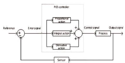
Figure 3. Block Diagram of PID Controller for Closed System
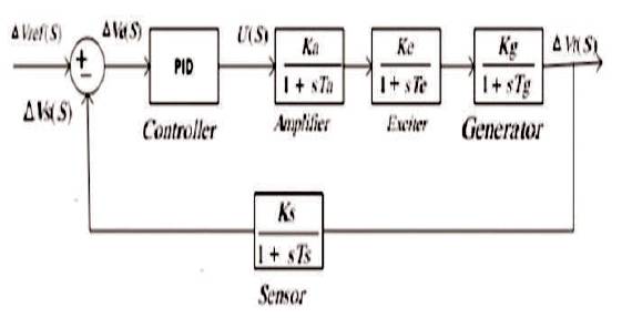
Figure 4. Transfer Function Model of AVR with PID Controller
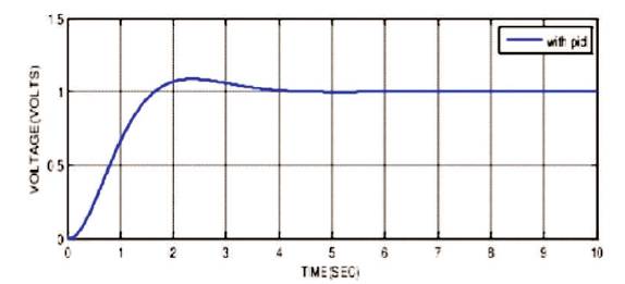
Figure 5. Response of AVR with PID Controller
In s-domain, the transfer function of PID controller is represented as,
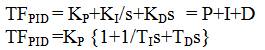
where, Kp , Kl , KD are the proportional gain constant, integral gain constant, and derivative gain constant, respectively, and Tl , TD is the integral implementation time/reset time and derivative implementation time/rate time, respectively.
In t-domain, the output of PID controller is represented as,
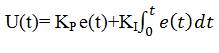
where u(t) is control signal given by the sensor and e(t) is error signal. For proper designing of PID controller, suitable tuning methods are required. The transfer function and parameter limit are given in Table 2. Various types of controller responses are compared in Figure 6.
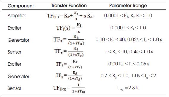
Table 2. Limit of Parameters involved in the Transfer Function used
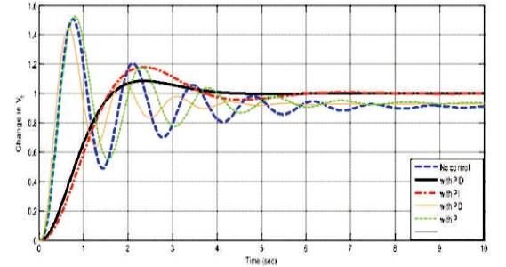
Figure 6. Comparison of Response of AVR with Different Controllers
In the last few years, fractional order control system and controllers have been implemented widely in many areas of science and engineering. The technique of Fractional Order PID controllers was firstly proposed by Podlubny in 1997. The fractional order control system is characterized by fractional order calculus. The FOPID controller is the extension of integer order PID controller.
Common definition used in fractional differo-integral is the Riemann-Liouville definition[6].
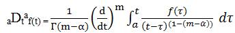
For m-1 < α < m, where Γ(.) is the famous Euler's gamma function. Another definition based on the principle of differo-integral is the Grunwald-Letnikov definition given by,
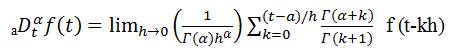
The authors can observe that by implementing the sign of fractional order operator αDtα f(t), the differentiator and integrator can be unified.
A new useful tool is the Laplace transform. The Laplace transform of an n derivative (n є R+ ) of a signal x(t) relaxed at t=0 is represented by: L{Dn X(t)}= sn X(s). So a differointegral equation gives both the signals u(t) and y(t) are relaxed at t=0 and can be represented in a transfer function form,
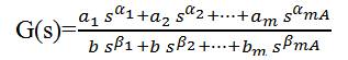
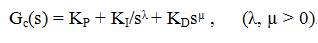
The well known form of a fractional order PID controller is “PIλDµ ” controller [16], containing an integrator of order λ and a differentiator of order μ, where λ and μ є any real number. The transfer function of FOPID controller has the form as,
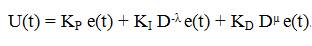
In t-domain the control signal u(t) is represented as,
It is clear that by selecting λ=1, and μ=1 a conventional PID can be obtained. Using λ=1, μ=0, and μ=1, λ=0 corresponds to classical PI and PD controllers, respectively. All these conventional types of PID controllers are peculiar cases of the PIλDµ controller. It can be supposed that the PIλDµ controller may amplify the system control performance.
There are a large number of tuning methods for controllers based on an open loop step response. However they all follow the same principle, they differ slightly in, how they derive the model parameter from the recorded output response, and also slightly differ as to combine suitable tuning constants to the model parameters.
The technique represented by Ziegler & Nichols [19] is based on a registration of open loop step response of control system, which is illustrated by two parameters. First obtained and a tangent at this point is drawn. The intersection between the coordinates and the tangent axis provide the parameter T and θ . Zeigler and Nichols provided PID parameters directly as a function of T and is given in Table 3. Response of PID tuned with Zeigler-Nichols is shown in Figure 7.
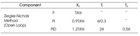
Table 3. Ziegler Nichols Open Loop Method for PID Controller
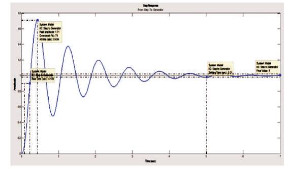
Figure 7. Step Response of AVR using PID Tuned by Ziegler-Nichols
The technique presented by Cohen & Coon is based on the controller settings on the three parameters θ, T & K of the open loop step response given in Table 4. Step response of AVR using PID tuned by Cohen-Coon is given in Figure 8.
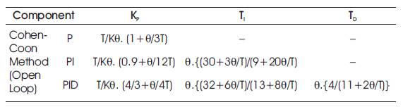
Table 4. Cohen Coon Open Loop Method for PID
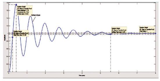
Figure 8. Step Response of AVR using PID Tuned by Cohen-Coon
The fractional order PID controller is based on fractional order calculus, which is an area of mathematics that concern with derivatives and integral of non-integer order. It is a generalization of conventional calculus that provide similar concepts and tools, but with higher applicability. Step response of AVR using FOPID is shown in Figure 9.
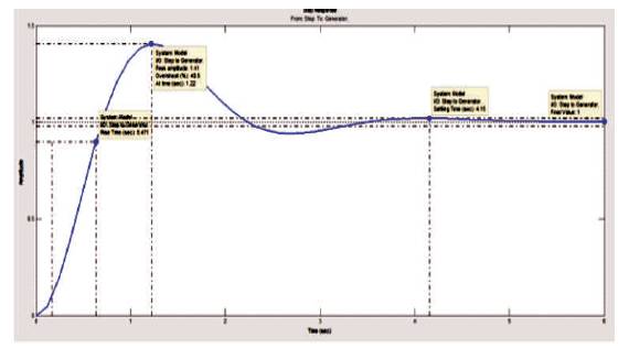
Figure 9. Step Response of AVR using FOPID
These tuning rules are acceptable only for systems that have s-shaped step response. Practically most results found with this optimization technique are satisfactory, but they greatly depend on initial estimates of control system's parameters given in Table 5.
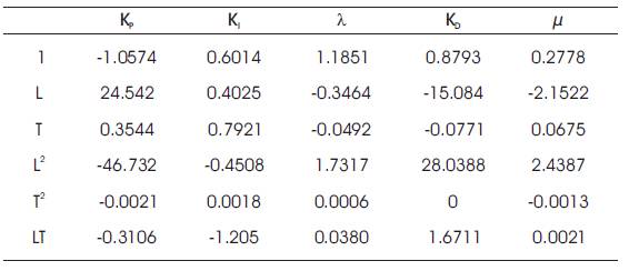
Table 5. Ziegler-Nichols Open Loop Method for FOPID
The Simulink model of AVR is given in Figure 10. This Simulink model comprises the mathematical function of exciter, amplifier, generator, and sensors.
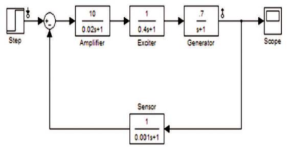
Figure 10. Simulink Model of AVR
Response of various tuning method for simulated model of AVR were observed, which are represented below.
Clearly, it can be seen from the comparison Table 6 that FOPID controller tuned by Zeigler-Nichols gives less overshoot as compared to the PID controller. The FOPID controller provides less settling time and also rise time is reduced. The FOPID controller leads to faster response of AVR. The response of PID tuned with Zeigler-Nichols and Cohen- Coon, and FOPID tuned with Zeigler-Nichols for AVR have been observed in Figure 11.
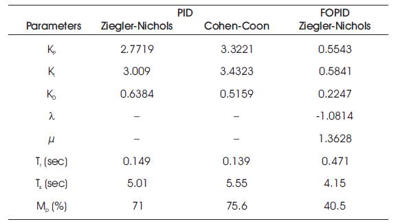
Table 6. Comparative Values of Different Parameters obtained by PID and FOPID Controllers
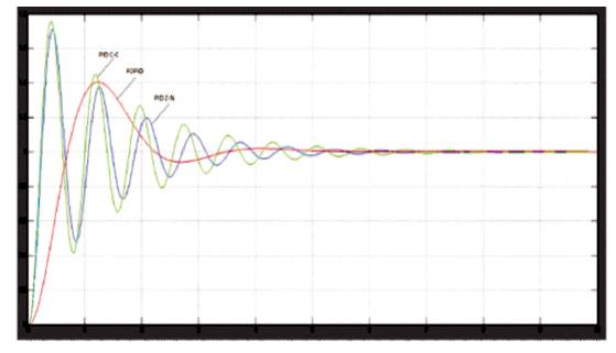
Figure 11. Response of PID tuned with Zeigler-Nichols & Cohen- Coon, FOPID tuned with Zeigler-Nichols for AVR
Comparison of performance of different FOPID and PID controllers has been observed and it is noticed that response of FOPID controller is superior than, PID controller. The settling time & rise time of the FOPID response is found to be lesser than PID controller. The fractional order controller may offer more adaptable time and frequency responses of the process control system, but this only occurs if the controller has more Degree-Of-Freedoms (DOF) than its integer order counterpart. The advantage of Fractional order models for real dynamical objects and functionalities become more and more understandable. From this paper, the authors ultimately conclude that the FOPID controller is better than other controllers. The Automatic Voltage Regulator concerned maintains the constant voltage up to a fixed level of load current, which, independent of generator speed and load and thus it improves the performance and life expectancy of the tools and equipments used in the power system. In this scheme, the time constant and gains of exciter, amplifier, generator and sensors have been changed to increase the robustness of AVR model and get a better response.