Figure 1. Proposed Defence System
Current technology is changing day by day, it is important for every nation to protect themselves from intruders. In this paper, the authors have developed a low cost robotic device capable of accurately and safely targeting and firing of an intruders who enters into a restricted. The main objective of this robotic system is to provide a best security system for “Border Security Force (BSF)” in order to eliminate the terrorists, also for star hotels, shopping malls, jewellery show rooms, etc. Where, there can be threat from intruders or terrorists. Since, human life is always precious, these robots are the replacement of fighters against terrorist in war areas. Firing of the targets takes place by the gun which can be automatically moved towards the target based on the proximity sensor arranged in some random places. This movement of the gun can be done automatically and manually.
This paper deals about new alternative version of a land mine. Before we deal about the system let us know a brief about land mine system in defence. A land mine is an explosive device, concealed under or on the ground and designed to destroy or disable enemy targets, ranging from combatants to vehicles and tanks, as they pass over or near the device. Such devices are typically detonated automatically by way of pressure from the target stepping or driving on it, though other detonation mechanisms may be possible described in [5]. The device may cause damage either by a direct blast or by fragments that are thrown by the blast. A land mine can be triggered by a number of things which includes pressure, movement, sound, magnetism and vibration. Anti-personnel mines commonly use the pressure of a person's foot as a trigger, but tripwires are also frequently employed. Most modern anti-vehicle mines use a magnetic trigger to enable it to detonate even if the tires or tracks did not touch it. Advanced mines are able to sense the difference between friendly and enemy types of vehicles by way of a built-in signature catalogue. This will theoretically enable friendly forces to use the mined area while denying the enemy access. But, there are so many gadgets available to detect these landmines and they can easily deactivated by enemies, so to avoid such type of things and to provide new safety techniques the authors have designed a model which can be used as an alternative to landmines. This system can be exclusively used in Border security Force (BSF).
In this proposed design, a robot that activates different functionalities in the robot based on the sensing of the gun by the proximity sensor and whole setup is shown in Figure 1. Now-a-days, terrorism and security have geared up. The chance of reducing the terrorism is not possible. But the steps can be taken to reduce the risk. The robot was developed to provide the security and to find the intruders entering into the restricted area [1,2]. With the help of sensors, the gun senses the intruders and the recommended activity is done automatically. The gun movement can be done manually and automatically. In the proposed system, the robot is developed which can be controlled through 8051 microcontroller. Proximity sensors can be used to sense the robot and fire automatically. Accelerometer sensor with gesture movements can be used to sense the robot manually. Robot is equipped with a gun and it can be controlled automatically and manually. Its bought under user control in manual mode. In automatic mode, the gun moves based on the sensor signal and the desired action is done based on the signal. When the intruder enters into the restricted area, the gun triggers automatically by the help of sensors which are fixed in some places of that area. Two sensors are placed in the right and left positions. When the right sensor is sensed, the gun moves clockwise and gun triggering takes place automatically. When the left sensor is sensed, the gun moves anticlockwise and triggering takes place automatically [3-9]. This triggering takes place manually by accelerometer sensor using gestures. By moving the hand right side, the gun moves clockwise and moving the left side, the gun moves anticlockwise, so that the user can have a feel like he is really controlling and triggering the weapon. The proposed design consists of two processes:

Figure 1. Proposed Defence System
The proximity sensors are placed in some random places and whenever the sensor detects person or object, it will send the data to the controller board and already the required programming part is done so that desired operation should be achieved as same as others [4- 10], finally the gun moves or targets the position of that sensor side and triggering will be done. Figure 2 shows the detailed version of working in the functional block diagram of automation process. For this part, the authors are employing the Arduino kit, motor driver kit, proximity sensors and DC motors. Power supply is interfaced to provide 9v supply to the kit and for sensors, the power supply is interfaced to provide 5v supply. One L293D driver is interfaced to ports (2 & 3), sensors are interfaced to ports (7 & 6) and gun trigger and motion motors are interfaced to ports (8, 9, 10 & 11).

Figure 2. Block Diagram of Automation Process
The authors also added the manual control mode for this system so that it can also work like the user's defined way and the system will be responding according to the hand gesture of the user. Finally the gun system will move left, right, up and down directions with respective hand gesture made by the user, so that the user can have a feeling that he/she is really controlling the gun system. Figure 3 shows the detailed version of working in functional block diagram. In this part, the authors employed the 8051 kit, motor driver kit, accelerometer sensors and DC motors. Power supply is interfaced to provide 9v supply to the kit and for sensors, the power supply is interfaced to provide 5v supply.
The Arduino Uno is a microcontroller board based on the ATmega328. It has 14 digital input/output pins (of which 6 can be used as PWM (Pulse Width Modulation) outputs), 6 analogue inputs [6], a 16 MHz ceramic resonator, a USB connection, a power jack, an ICSP header, and a reset button. It contains everything needed to support the microcontroller; simply connect it to a computer with a USB cable or power it with an AC-to-DC adapter or battery to get started. Figure 4 shows the mother board which is used in the system.

Figure 3. Block Diagram of Manual Process

Figure 4. Arduino Mother Board
In this part, the authors employed P89v51RD2 micro controller which comes under 8051 family. It is equipped with a 64kB flash memory and 1024 bytes of data RAM. Figure 5 shows the Microcontroller kit which is used in the system. Signal from sensor will get converted from analogue to digital signal as described in [6].

Figure 5. 8051 Microcontroller Kit
L293D driver is à 16 pin Motor Driver IC which allows DC motor to drive in either directions [7-9]. It can supply a maximum current of 600mA per channel. In the proposed system, L293D is integrated in the kit itself which is used as shown in Figure 6.

Figure 6. Motor Driver Setup Sensors
A proximity sensor often emits a beam of electromagnetic radiation (infrared, for instance), and looks for changes in the field or return signal. The object being sensed is often referred to as the proximity sensor's target. Different proximity sensor targets demand different sensors. For example, a photoelectric sensor might be suitable for a plastic target an inductive proximity sensor which always requires a metal target, and Figure 7 is showing the operation of the sensor.

Figure 7. Operation of Proximity sensor
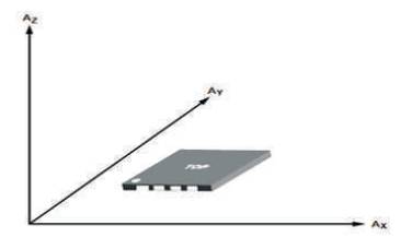
An accelerometer measures gravitational force or acceleration. By tilting an accelerometer along its measured axis, one can read the gravitational force relative to the amount of tilt. Most accelerometers available today are small surface mount components, so you can easily interface them to a microcontroller. There are three axes that can be measured by an accelerometer and they are labelled as X, Y and Z which is shown in Figure 8. Each measured axis represents a separate Degree of Freedom (DOF) from the sensor—thus a triple axis accelerometer might be labelled as 3 DOF. In this paper the authors take only 2 axes namely X and Y which are used.

Figure 8. Operation of Accelerometer Sensor
Operation of the system requires the following software
Simulation is used for hardware configuration and can write and test applications before hardware is available.
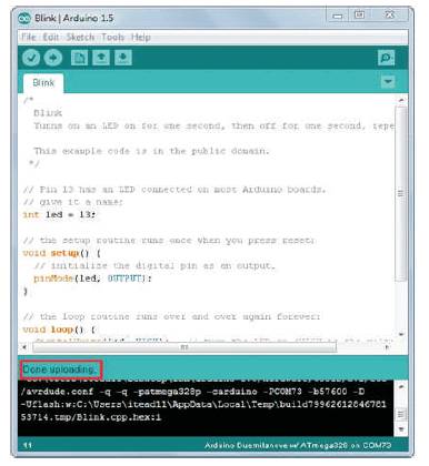
Arduino software is used to write the code for the movement of the gun automatically by sensors. Program is written in C language [8]. Arduino is a tool for making computers that can sense and control more of the physical world than your desktop computer. It's an open-source physical computing platform based on a simple microcontroller board, and a development environment for writing software for the board. Arduino can be used to develop interactive objects, taking inputs from a variety of switches or sensors, and controlling a variety of lights, motors, and other physical outputs. The Arduino programming language is an implementation of wiring, a similar physical computing platform with sample programming code shown in Figure 9, which is based on the Processing multimedia programming environment. By using this software, the gun can be controlled automatically by dumping the code into the Arduino hardware using the USB connected to the PC.

Figure 9. Sample programming at Arduino Software
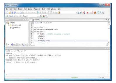
For the manual process of the robot, the authors used keil software. In order to write, compile and convert code to the corresponding hex codes you must build a project in the keil Micro vison software as shown in Figure 10, window of software. Keil development tools for the microcontroller architecture support every level of software developer, the professional applications engineer to the student for learning about embedded software development. Keil is used to solve the complex problems facing embedded software developers. Flash Magic is a free, powerful, feature-rich Windows application that allows easy programming of microcontrollers.

Figure10. Sample programming of keil software
Recent days, India is sick off with massive terror attacks, which cannot be stopped. But it can be reduced by technological power. So it is necessary to design a model of an apt robot that meets combatant needs. So to avoid terror attacks, to ensure more security at the border and high density areas, it's necessary to maintain a world class military technology in accordance with combatant needs. Even every nation needs its own defence system for their integrity and security. In such a way, construction of these robots will carry nation's name, fame globally. To increase the utility of a robotic system in the eyes of an agency purchasing a robotic system, more functionality must be added, and price must be decreased. Implementation of this device will give the Land Shark the capability to exert nonlethal force on its environment and aid it in carrying out the various types of missions that it might be assigned.