The objective of the paper is to design a more efficient model of a Vertical Axis Wind Turbine using advanced tools like Modelling, simulation and CFD analysis. It includes some advanced optimised design techniques. This concept is developed based on existing Savonius and Darrieus wind turbine models. To develop modified Savonius turbine and to analyze and compare its feasibility as an alternative method for harvesting wind energy at highest efficiency, in this paper, it is going to be replaced with a Savonius rotor blade with FIVE naca-0009 airfoils each side, which controls the motion of airfoils while the turbine rotor rotates. These Airfoils will be in closed condition when rotor is facing the direction of air stream and when the rotor blade comes in opposite direction to the wind, the three middle blades open by which the opposing Drag force will decrease inturn increasing the efficiency of VAWT.
It is envisaged that the proposed Modified Savonius turbine will compare favorably with current systems in the areas of power output and cost effectiveness [18]. The ratio of power output from the device to the total wind power in the cross section occupied by the device will be used as the basis of comparison when comparing the proposed system to others currently in use. The main drawback of Savonius is its low efficiency; this is due to the opposing force of opposing blade with the free stream [5].
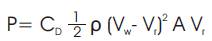
The power generated from drag force is given by formula,
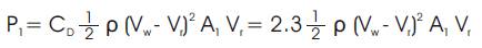
The power generated from drag force in the direction of wind (convex side),
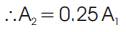
Power generated from drag force in the direction opposite to wind (concave side),

Note: The area on the opposing side is reduced by 75 % by providing movable blades
Finally the resultant drag power generated from Savonius turbine,
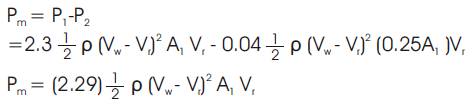
Where Vw is speed of wind and Vr is relative speed.
In design of VAWT the first issue comes with design of Airfoils that is to be placed in Savonius turbine. In this project the authors used a NACA 0009 model airfoil [1].
Details of Airfoils for the model are as given below:
| Chord | = | 184 mm |
| Airfoil Thickness | = | 9% C |
| Thickness location | = | 30% C |
| Camber | = | 0% C |
| Camber location | = | 40% C |
These values are taken by considering the swept area of turbine to be ~1sq.m. The design of turbine with above values is given in Figure 1. By considering the above values into consideration, the air foil is created in UniGraphics.
Figure 1 shows each side (convex and concave) of rotor consisting of 5 blades. Out of which only 2, 3 and 4 numbered airfoils are movable and 1 and 5 are fixed airfoils [16].
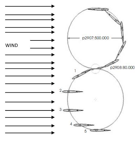
Figure 1. Complete Airfoil assembly dimensions
These blades will rotate when the concave side of the rotor faces the wind to minimize the opposing force of rotor on wind as shown in Figure 1. In this, blade 2 will rotate through 600, blade 3 will rotate through 950 in clockwise direction and blade 3 will rotate through 400 in anti-clockwise direction. These movements are shown in Figure 1 [10].
The efficiencies of vertical axis wind turbines for two different shapes of movable blades i.e., symmetrical and cambered airfoils are analysed. After some basic analysis and optimization, it is confirmed that the symmetrical blade arrangement is having more efficiency than the cambered airfoil arrangement.
Efficiency of the turbine is determined by using Ansys CFD simulation. In Ansys has used different input parameters which are given below [8].
CFD analysis is an advanced mathematical tool for fluid flow analysis. The wind flow effects are evaluated using CFD package i.e., Ansys CFX [3].
| Software used | - | Ansys CFX [9]. |
| Input Velocity | - | 14.0 m/s |
| Flow type | - | isothermal, steady flow, turbulence 5% |
| Fluid Type | - | air at 25oC |
| Test Rig | - | Vertical axis wind turbine |
In symmetrical airfoils, there are different types of airfoils available. But to get more accurate results, reference is taken from the energy report released by Sandia National Laboratories on Lift forces, Drag forces and momentum of different NACA airfoils for an angle of attack from 0 to ± 180° [11]. After optimizing these results, NACA-0009 airfoil has been used for this work. This is because of its high lift and low drag values in the range of angle of attack [12] (Figure 2). Figure 3 shows the assembled axis vertical wind turbine.
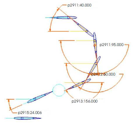
Figure 2. Angle of Attack of different airfoils
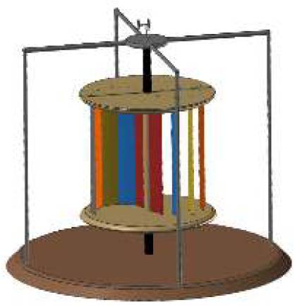
Figure 3. Assembled Axis Vertical Wind Turbine
| Velocity at exit of turbine on concave side | - | 9.0976 m/s |
| Velocity at exit of turbine on convex side | - | 14.263 m/s |
| Cp of VAWT at O0 AOA with reference to NACA airfoil | - | 0.5105 |
After the completion of the simulation the values of Wind speeds are utilized to calculate the Cp of the turbine using the formula,
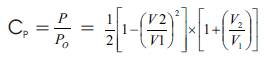
Using the above formula, the Cp value is 0.5105. Figure 4 shows the velocity counters of VAWT.
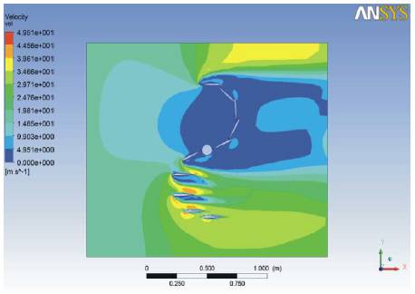
Figure 4. Velocity counters of VAWT
The existing design of Vertical Axis Wind Turbine has low efficiency at present. The modified blade design with aerodynamic profile has increased the efficiency comfortably. Due to controlling of a blade movement, the negative effect on the concave blade is reduced to a significant value. Hence efficiency of the system is increased and it has been tested successfully. The results in simulation are encouraging. According to the work on this paper, the results show that after the modification of the vertical axis wind turbine basic design by putting airfoils in a drag based wind turbine, a very significant coefficient of power (CP) value is observed .
It can be concluded by this research, that these vertical axis wind turbine are more suitable for house hold purposes than the horizontal wind turbines and they can work with a very low wind speed coming from all the directions making them suitable for urban areas.Till now the Savonius turbine is used for low power generation requirements but by putting the movable blades in this turbine we can use it for large scale power generations also. Because of its decrease in opposing force to the wind direction, it works more effectively than the classical Savonius wind turbine in large scale power generations.