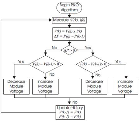
Figure 1. Flowchart of the P&O Algorithm
In this paper, the MPPT (Maximum Power Point Tracking) with resistive load is implemented in MATLAB with output sensing direct control method using Cuk converter. The simulated system consists of the BP SX 150S photovoltaic (PV) module, the ideal Cuk converter, the MPPT control, and the resistive load (6Ω). The selection of the Purturb & Observe (P&O) algorithm permits the use of output sensing control method which eliminates the input voltage and current sensors. The direct control method adjusts the duty cycle within the MPP tracking algorithm. The way to adjust the duty cycle is totally based on the theory of load matching. When the value of Rload matches with that of Ropt , the maximum power transfer from PV to the load will occur. These two are, however, independent and rarely matches in practice. The goal of the MPPT is to match the impedance of load to the optimal impedance of PV.
Energy generated from clean, efficient, and environment friendly resources has become one of the major challenges for engineers and scientists [1]., [2] Among all renewable energy sources, photovoltaic power systems attract more attention while greenhouse emissions are reduced [1-4] .Regarding the endless aspect of solar energy, it is worth saying that solar energy is a unique solution for energy crisis. However, despite all the aforementioned advantages of solar power systems, they do not present desirable efficiency [5], [6]
The environmental effects such as temperature, irradiation, special characteristics of sunlight, dirt, shadow, and so on affect the performance of the photovoltaic (PV) system [7],[8].Changes in insolation on panels due to fast climate changes such as cloudy weather and increase in ambient temperature can reduce the PV cell output power [9], [10]
The PV system has poor efficiency so it operates at the Maximum Power Point Tracking (MPPT). There are a large number of algorithms that are able to track MPPs. Here Purturb and Observe (P&O) algorithm [11-24]is recommended because of their simplicity and ease of implementation
In the P&O algorithm [25-27] the operating voltage of the PV array is perturbed by a small increment, and the resulting change in power, ΔP, is measured. If ΔP is positive, then the perturbation of the operating voltage moved the PV array's operating point closer to the MPP. Thus, further voltage perturbations in the same direction (that is, with the same algebraic sign) should move the operating point toward the MPP. If ΔP is negative, the system operating point has moved away from the MPP, and the algebraic sign of the perturbation should be reverse to move back toward the MPP [21]. The advantages of P&O algorithm are simplicity and ease of implementation. The P&O MPPT algorithm which is shown in Figure1 has been implemented in MATLAB to track maximum power from the solar PV module.
Figure 1. Flowchart of the P&O Algorithm
The PV cell converts energy in the photons of sunlight into electricity by means of the photoelectric phenomenon found in certain types of semiconductor materials such as silicon and selenium [1]
PV module characteristics are comprehensively discussed in [1][4] [8] [18] [36] [37]which indicate an exponential and nonlinear relation between the output current and voltage of PV module. The main equation for the output current Io of a module is [8]
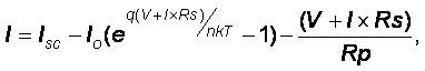
Where: Isc is the short-circuit current that is equal to the photon generated current, Io is the reverse saturation current of diode (A); q is the electron charge (1.602× 10⁻¹⁹ C); V is the voltage across the PV cell (V); k is the Boltzmann's constant (1.38×10⁻²³ J/K); T is the junction temperature in Kelvin (K) n is known as the idelity factor and takes the value between 1 and 2. Rs and Rp are series and parallel resistance respectively.
Since a single PV cell produces an output voltage of less than 1 volt, it is necessary to string together a number of PV cell in series and parallel to achieve a desired output voltage. Generally, 36 cells in series will provide a large enough voltage to charge a 12 volt battery, and 72 cells would be suitable for a 24 volt battery. For simulation the BP SX 150S PV module, which contains 72 cells, was chosen in this paper. The electrical parameters are tabulated in Table 1, and the resultant curves [38] are shown in Figures 2 and 3. It shows the effect of varying weather conditions on MPP (shown by * on various irradiances) location at I-V and P-V curves.
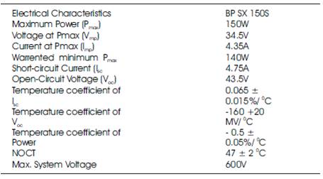
Table 1. Parameters of BP SX 150S Solar Module (G O = 1KW/M2 , 250 C)
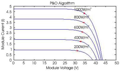
Figure 2. I-V Curves for P&O Algorithm at Various Irradiances
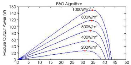
Figure 3. P-V Curves for P&O Algorithm at Various Irradiances
Cuk converter topology is the most suitable switch-mode dc to dc power converter, called a maximum power tracker, used to maintain the PV module's operating point at the MPP [25], [28-30].Cuk converter has low input current ripple, suitable to implement a system capable of measuring the I-V curve of PV module (from open-circuit voltage to short-circuit current).
The output sensing method measures the power change of PV at the output side of converter and uses the duty cycle as a control variable [1] .The MATLAB simulation illustrates the relationship between the output power of converter and its duty cycle. In the simulation, BP SX 150S PV module [31] is coupled with the ideal (loss-less) Cuk converter with a resistive load (6Ω). The duty cycle of converter is swept from 0 to one with 1% step [3], and the output power of converter is plotted in Figure 4 [32] As shown in Figure 4, there is a peak of output power when the duty cycle of converter is varied. This control method employs the P&O algorithm to locate the MPP [25-27]. Figure 5 shows the flowchart of P&O algorithm for the output sensing direct control method. In order to accommodate duty cycle as a control variable, the P&O algorithm used here is a slightly modified version from that previously introduced [32] but the idea how it works is the same. The algorithm perturbs the duty cycle and measure the output power of converter. If the power is increased, the duty cycle is further perturbed in the same direction; otherwise the direction will be reversed. When the output power of converter is reached at the peak, a PV module or array is supposed to be operating at the MPP [25-30], [32]. This control method only works with the P&O algorithm and its variation, and does not work with incCond algorithm.
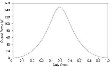
Figure 4. Output Power of Cuk Converter vs. Its Duty Cycle (1KW/m2 , 25oC)
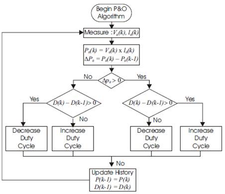
Figure 5. Flowchart of P&O Algorithm for the output Sensing Direct Control Method
The direct control method which is shown in Figure 6 is simpler and uses only one control loop, it performs the adjustment of duty cycle within the MPP tracking algorithm. The way to adjust the duty cycle is totally based on the theory of load matching.
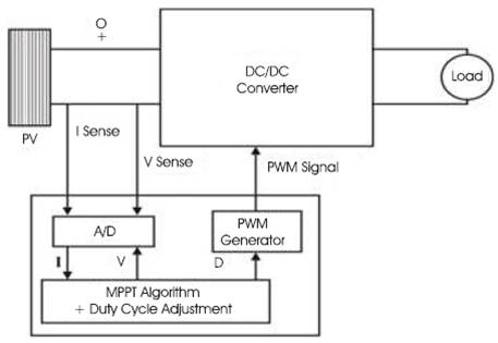
Figure 6. Block Diagram of MPPT with Direct Control
When proposing the MPPT, the major job is to chose and design a highly efficient converter, which is proposed to operate as the main part of the MPPT. The efficiency of switch-mode dc-dc converter is widely discussed in [2]. The Cuk converter has low switching losses and the highest efficiency among non isolated dc-dc converters. It can also provide a better output-current characteristic due to the inductor on the output stage. Thus, the Cuk configuration is a proper converter to be employed in designing the MPPT [1], [2], [32].
The Cuk converter and its operating modes [1], is used as the power stage interface between the PV module and the load. The Cuk converter has two modes of operation. The first mode of operation is when the switch is closed (ON), and it is conducting as a short circuit. In this mode, the capacitor releases energy to the output. On the second operating mode when the switch is open (OFF), the diode is forward-biased and conducting energy to the output. Capacitor C1 is charging from the input [1]
The relation between output and input currents and voltages are given in the following [1], [32] [33]
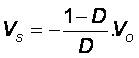
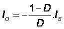
Where Vs and Vo are the input and output voltages of the Cuk converter respectively, Is and Io are the input and output currents of the Cuk converter respectively, D is the duty cycle (0 < D< 1 ). Some analysis of Cuk converter specifications are provided in [34] and comparative study on different schemes of switching converters is presented in the literature [35].The duty cycle (D) for the Cuk converter used in simulation was selected as 0.1 < D> 0.6.
PV is directly coupled with a load; the operating point of PV is dictated by the load. The impedance of the load is described as below
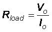
Where: Vo is the output voltage, and lo is the output current. The optimal load for PV is described as:
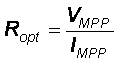
Where: V MPP and IMPP are the voltage and current at the MPP respectively. When the value of Rload matches with that of Ropt , the maximum power transfer from PV to the load will occur. These two are, however, independent and rarely matches in practice. The goal of the MPPT is to match the impedance of load to the optimal impedance of PV. From the equation (1) and (2), the input impedance of the converter is:
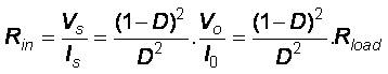
As shown in Figure 7, the impedance seen by PV is the input impedance of the converter (Rin ). By changing the duty cycle (D), the value of Rin can be matched with that of Ropt.
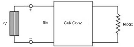
Figure 7. The impedance seen by PV is R that is Adjustable in by Duty Cycle (D)
Therefore, the impedance of the load can be anything as long as the duty cycle is adjusted accordingly
The direct control method is implemented with P&O algorithm using Cuk converter and the simulation is performed under the linearly increasing irradiance varying from 200W/m2 to 1000W/m2 . Figures 8(a) and (b) of the P-V and I-V curves show that the trace of operating point is staying close to the MPPs during the simulation. Figure 8(c) shows the relationship between the output power of converter and its duty cycle, the maximum output power is 150W at duty cycle (D) = 4.5. Figure 8(d) shows the current and voltage relationship of converter output. Since the load is resistive, the current and voltage increase linearly with the slope of 1/Rload on the I-V plane. It shows that maximum output current is 5A at 30V.
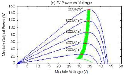
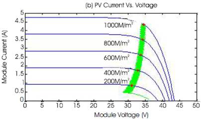
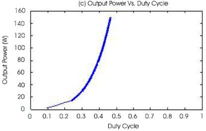
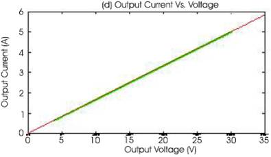
Figure 8. MPPT Simulation with Direct Control Method (P&O Algorithm)
In recent years it is very important to concentrate on renewable energy resources. In renewable energy resources solar energy is most reliable and cheap in cost. In power system, it is important to get optimum power from the system.
In this paper the authors concentrate the method which is helpful to get MPP. In recent years the P&O (MPPT) algorithm plays vital role to achieve MPP. Hence in this paper direct control method (P&O algorithm with duty cycle adjustment) is implemented.
Simulation results are obtained using MATLAB simulation for different values of irradiance by adjusting duty cycle of the dc-dc converter (Cuk converter). It is observed that the curves obtained by direct control method are better than simple P&O algorithm for PV module