Figure 1. System Architecture
Lift irrigation method is a method followed in water scarce areas, where the underground water source is tapped for irrigation of agricultural fields. This process is automated to achieve a greater control over the parameters of importance and by that way increasing the efficiency of the entire process. In the integrated approach of automation, the whole system is considered and the individual modules used have a dependency over the other. Thus integrated method requires maintenance of all the modules in high efficiency to effectively gain the advantages of the method. The expected result of this approach is a central and local control system for the process and to develop a controller program which is more user-oriented. The comparative results of the existing process with the developed approach show a great variation in the ease of troubleshooting the process and also the monetary difference in maintaining the system. Analysing the results, about 20% difference in maintenance time is found out considering for a month.
The water lifting technique was implemented a very long time back for the domestic purpose. Later, when the larger underground source of water was found, this method was extended to irrigation of agricultural lands. But, the earlier source of power for lifting the water is either human energy or by using animals. Hence by this method, only a small amount of water was able to retrieve in a greater time. To compensate this drawback, the electro-mechanical method was initially integrated to this method which uses pumps to lift the water. But the issue pertaining with this method was that the entire system can be implemented only for smaller fields since the process control is still manual. The other major factor recommending the work is to get a low wastage system compared to the existing one. Automation of the process to get higher results was considered as the solution. The main objective of the work is to develop an highly integrated automation technique for lift pumping station control.
The term automation is generally constituted for any method, which reduces completely or a major amount of direct human intervention. Thus, the same method with the aid of new mechanical components will be developed with a much higher yield output [1]. But the common misconception about automation of a process is that by just automating a system, the results need not be to the expected level. If the result is not up to the expected level, the basic necessity of automation cannot be achieved which may result in financial loss, since the investment amount is generally high in automating a process [2]. Thus the required method of automating a control process is of an integrated approach which should be able to control the entire system as a single unit.
The term ‘Integrated Automation’ is coined to describe the process of automating a process control field with all the tenets of automation. The common problem identified in any process control field is the lack of control of either local or central in nature. This creates time lag between the implementation of each step. The other issue faced is during troubleshooting of the plant, the controller program developed will be of integrator oriented rather than process oriented. Because of this, editing a program according to the plan requirement takes a large amount of time. These problems are solved by implementing the integrated approach which uses modules like logical controller programming, Human-machine Interface (HMI) and a supervisory central SCADA (Supervisory Control and Data Acquisition) [3, 4]. Hence by this way, a complete control of the process can be achieved, which gives an effective maintenance and reduces the loses occurred.
The tenets of automation included in this method are Programmable Logic Controller (PLC), Human-Machine Interface (HMI) and Supervisory Control and Data Acquisition (SCADA). Though all are basic components of automation, the way they are tweaked to get an effective output is through effective simple programming and screen development.
The present system deals with effective integration of the individual unit of automation in order to improve the efficiency of the implemented system when taken as a whole. The improvisation in the tenets of automation is expected to yield a considerable amount of difference in the system.
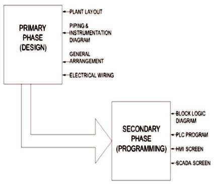
The design and programming of the method can be implemented in two steps which consist of initial development phase and then the programming phase. The design phase basically consists of manipulation of effective design document which should explain the plant structure and the corresponding components position with its relative connection with other components. The main control panel unit with the devices assembled are developed in this phase. The second phase is of programming phase which is of effective controller programming [5] and HMI [6, 9], SCADA screen development. The overall system structure is shown in Figure 1.
Figure 1. System Architecture
The initial design phase consists of developing several documents based on which the physical structure is developed. The main structure taken into consideration is the plant layout, instrumentation diagram, control panel arrangement and electrical connections. The primary phase is depicted in Figure 2.

Figure 2. Design of the Primary Phase
The programming phase consists of the controller programming which should be simple and direct hence more of user-oriented rather than integrator oriented. The HMI acts as the local control unit and is the direct display unit available for the on-site manager. SCADA acts as the single central control unit for all the cluster of pumping stations under consideration. Thus, the screens should contain all the values required and should also add an aesthetic nature to the system.
The integrated automation of the pumping station can be implemented in the sequence of initial designing phase and the programming phase. The methodology used for the study of the system is as shown below:
Step 1:
Understanding the Plant Layout.
Step 2:
Developing the 3D layout of the plant with multiple views.
Step3: Defining the pump house. Modules included in the Pump house.
Step 4:
Develop P&ID.
Step 5:
Design Control Panel and Electrical Wiring of the panel
Step 6:
Study the Control Philosophy. Design the Block Logic Diagram.
Step 7:
Generate PLC program.
Step 8:
Local Control Module (HMI screen).
Step 9:
Central Control Unit (SCADA development).
The design of the system includes developing the plant layout initially to understand the exact physical nature of the plant. The 3D layout with animated scenes help in understanding different views of the plant based on which the relating parameters can be designed. The pump house unit in the plant acts as the major actuating unit since all the working pumps, control panel with local control module are contained in it.
The control section designing of the system deals with the development of the control panel and the piping and instrumentation structure. The initial General Arrangement diagram (GA) gives the physical structure of the panel and are developed based on the locations of each unit of the modules present in the control panel. Some of the components used in the control panel are as follows:
i) PLC- Compact Logix
ii) AENT- For additional point I/O's
iii) Relay Cards- Digital Outputs
iv) Terminal Blocks
v) HMI- Local control unit
The electrical wiring of the panel is done based on the drawing developed separately for 24 VDC as well as 230 VAC. The wiring is done following the standards defined including the color coding of the wire for each type of connection. The wiring diagram is developed for the instrument connection, terminal block connection as well for the measuring devices mounted on the control panel door.
The physical installation of the instruments will be done based on the hook-up diagram [7, 10] of the particular instrument. The hook-up diagram is shown in Figure 3.
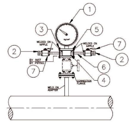
Figure 3. Hook-up Diagram
The hook-up diagram of the instrument with its specifications as tabbed in Table 1 contains the piping dimensions and the reducer or expander dimension. The diagram helps in installing them since the piping installation will be done initially and then the instruments will be installed.
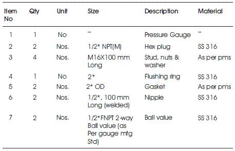
Table 1. Instrument Parts (of Figure 1)
The main three facets of automation include the logical controller, machine interface as well as the supervisory control unit. Thus integrated automation can be implemented if all three modules communicate with each other forming an error free system with maximum control over the process. Thus the programming section includes developing the PLC (Programmable Control Logic) program and the screens for HMI and SCADA.
The prime objective of PLC program development is to generate a user oriented simple program rather than integrator oriented program. But, the security aspects for the program should be considered since the access to the program editing can be allowed only to authorized personnel. The PLC program is developed in ladder logic style, which is the most common and widely used programming method. The ladder diagram is developed in different windows separately giving each control action of the system. Thus it helps the user to identify the location in the program easily. Figure 4 shows the ladder logic diagram of the program.
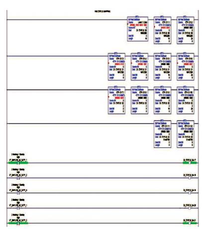
Figure 4. PLC Ladder Diagram
The programing is done to control the sequence of operation of the pumps, mode selection (Auto mode and Manual Mode) and control the actuating devices through command. All the input received from either the field instruments or the HMI unit are assigned an individual input tag and the corresponding output is given to the actuating devices in the field or through a display in HMI.
The Human-Machine Interface (HMI) module acts as the local control module present in the control panel. The unit allows the local site operator to control [7, 9] the process and hence small corrections if any can be done by the operator rather than going through the central control. Thus it saves time as well as gives immediate control over the process for the operator. The HMI also contains the alarm notification screen as well as the log screen which gives alarm if any process deviated from the actual requirement. Figure 5 illustrates the alarm summary screen which helps in alerting the operator quickly.
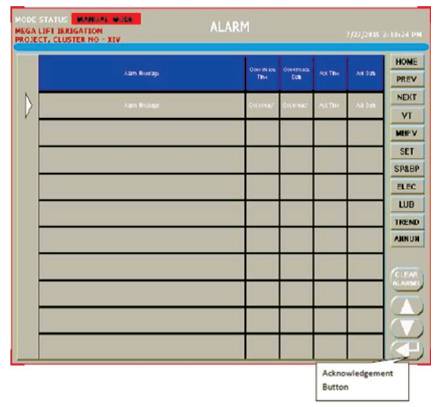
Figure 5. HMI Alarm Summary
The supervisory control of the process is done by using SCADA system which acts as the central control. The SCADA is able to control and collect data for multiple number of pumping stations. The main function of the SCADA system is to monitor the process [8] and intimate if any discrepancy is found over the working. The faceplate screen developed for each instrument and component of the system helps to get the current value of the component. Thus, the faceplate screen acts as the pop-up and helps to save the processing memory since they can be initiated as and when required. Faceplate in the SCADA is shown in Figure 6.
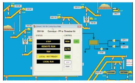
Figure 6. SCADA Faceplate
The expected outcome of this method is achieving a high end fool-proof method of automation which spreads is controlled on all the units under the system. The separate local [10] and central control unit helps to gain an upgraded control from work-site as well as from central control office.
The existing method of automating the lift pumping station is found to be lacking in full system control and thus the process is controlled only either through local control or through central control. The local control method is the preferred one, but by this method control and monitoring of multiple stations becomes difficult and hence direct intervention is required for each station. On systematic implementation of the method, the process automation can be done in local mode as well as centralised mode and provides an easy user oriented program. The accessory documents in the design stage such as P & ID, General Arrangement Drawing etc., helps to develop the system in a step by step manner without much time lag.
The new industrial scenario expects time bound high controlled approach for every sector and especially in process control the wastages is to be reduced up to the minimum level possible. To achieve it practically an effective automation solution is required. Thus integrated automation of process control fields gives many advantages over the existing method of automation of the system. The comparative results show the difference of about 20% in quantitative terms which justifies the requirement of such an automated approach.