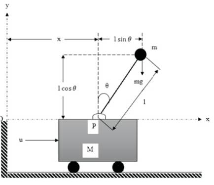
Figure1. Inverted Pendulum Cart System
The Inverted Pendulum (IP) system is a classic control problem which is used as benchmark and is easily available in laboratories to verify new control techniques evolved. The main aim of this paper, is to develop a controller to keep the pendulum upright and cart at desired position. In this paper, feedback linearization control technique is used to eliminate non linearity of this system and compared with conventional PID (Propositional- Integral- Derivative) controller. The MATLAB Simulink model has been developed for simulation, control and analysis of IP system. The result shows that the cart position and pendulum angle both acquired desired position quickly.
The Inverted Pendulum (IP) system is an inherently unstable, highly nonlinear and coupled, and Single Input Multi- Output (SIMO) system which is treated as typical nonlinear control problem [1,2. This is a benchmark for designing, testing, evaluating and for comparison of various control methods. Since this system is highly nonlinear and unstable, it is best suited for the control engineers and the researchers working on development of new control techniques. The control of IP has become a popular control problem in the field of control engineering because it is the most difficult system being inherently unstable and highly nonlinear. So this system became a choice of dynamic system for analysis of its dynamic model and develop a control law. The aim of this research is to stabilize the inverted pendulum and the cart position on the track to be controlled quickly, smoothly and accurately to keep the pendulum as always in upright position during the movement. Realistically, this mechanical system is representative of a class of altitude control problems whose aim is to maintain the desired vertically oriented upright position at all times [2, 3]. The control problem is to obtain dynamic models of system, and using these models to develop control law to achieve desired result.
The system used in this paper is inverted pendulum system. The main difficulty in this kind of system is that it is difficult to satisfy by linear control methods such as PI, PID etc., in all the conditions. The recent development in the area of Artificial Intelligence (AI) techniques has given novel solution to different typical control system problem [2- 4]. PID and FOPID (Fractional Order Propoutional - Integral- Derivative) have been applied for optimization and tracking control problem of inverted pendulum system and Particle Swarm Optimization (PSO) as used in [4].
There are different Artificial Intelligence (AI) techniques, such as Fuzzy Logic Theory (FL) [2,5], Artificial Neural Network (ANN),and evolutionary computational methods, as Genetic Algorithm (GA), PSO [4], etc. All these techniques are known as intelligent computational techniques which gives novel and more accurate solutions to various control problems.
Adaptive Control is a set of techniques for automatic adjustment in real time of controllers in order to achieve or maintain a desired level of performance of a control system. In [7, 8] adaptive control technique of control system is explained and there are different techniques of adaptive control method. The Model Reference Adaptive Control (MRAC) approach and application is shown in [9, 10, 11, 13, [14]].
PID (Proportional-Integral-Derivative) control technique gives the simplest and efficient solution to many control problems. There are three terms proportional, integral and derivative in PID controller. The increase in proportional term increases the speed of response and improves accuracy but the stability deteriorates. The derivative improves the stability of the system and enables increase in gain and decrease in time constant which increases the speed of the response but has no impact on steady state accuracy. The integral term reduces the steady state errors but the speed of response decreases and stability deteriorates. And the derivative term improves the transient response. Thus the PID controller improves both the transient and steady state response [4, 6].
In this work, PID control system is used to control the nonlinear model of IP system. Two controllers are used to stabilize cart position and pendulum angle, one for cart position and another for pendulum angle [[1-4]].
The feedback linearization control technique is also used to make the inverted pendulum system linear and stable. The linear techniques state feedback etc. are not proved to be suitable for non-linear IP system. Feedback linearization cancels the nonlinearities and make the system stable. The controller is developed using control law [15, 16].
The comparative performance analysis of PID control and feedback linearization control for IP system is presented in this paper. There are two main aims of this paper, the first is to develop a model of the inverted pendulum system and the second is to develop a PID controller which determines the correct control action to stabilize the system and then to develop feedback linearization controller.
This paper has been organized as follows. Section 1 presents the mathematical modeling of the inverted pendulum-cart system. Section 2 describes the control methodologies which have been used to stabilize the pendulum upright and cart at desired position. Section 3 describes, MATLAB Simulink models of the inverted pendulum system and simulation results have been presented. Conclusions are given in the last section.
The free body diagram of an Inverted Pendulum (IP) placed on the cart is shown in Figure 1. [[2-4], 17].The IP system is composed of a cart and a pole hinged vertically upward on it. The mathematical model equation of this non-linear Inverted Pendulum (IP) system can be derived. The rod is assumed massless and the cart is frictionless.
Figure1. Inverted Pendulum Cart System
The mass of the cart is represented as M and m denotes the mass of the pole. There is an external force, u(t), in xdirection which works as control force on cart and a force due to gravity acts at the point mass all the time. In Figure 1, x represent the cart position and θ is the angle of the pendulum rod w.r.t. the vertically upward direction.
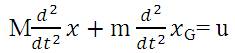
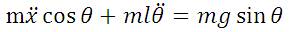
A force balance in the x-direction explains that the external force applied on the system is the summation of the mass times acceleration of the cart and the mass times the xdirected acceleration of the point mass. Force balance equation is written as:
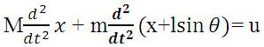
Where, M is the time dependent center of gravity coordinates of the point mass, (x G, yG). For point mass it is assumed, that the location of the centre of gravity of the pendulum mass is,

Where, l is the length of pendulum rod. Putting equation (2) into equation (1) we get:

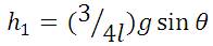
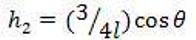
Similarly, a torque balance on the system is performed, where torque is the product of the distance to the pivot point (the length of arm l) and the perpendicular component of force.
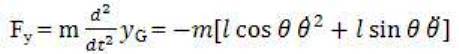
In this case, the torque on the mass due to the acceleration force and due to gravity force is balanced. The torque balance eqn. can be written as:

Where, Fx , and Fy are the horizontal and vertical component of force determined as:

Substituting equation (6) and equation (7) into equation (5) we get
These two eqns. definitely represent a nonlinear complicated dynamic system.
Putting equation (8) into equation (4) we get:

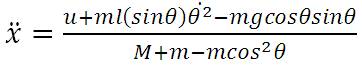
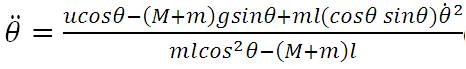
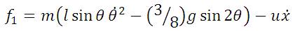
Finally, we get two nonlinear equations, equations 10 and 11.
The two nonlinear dynamic equations of Inverted Pendulum system are
PID controller and feedback linearization control techniques have been applied to stabilize the IP system. Both the techniques have been described below.
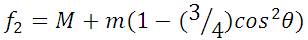
The Controllers are used to stabilize the unstable system. The block diagram of PID control of the Inverted Pendulumcart system is shown in Figure 2. As shown in Figure 2, IP system is controlled by two separate controllers: pendulum angle controller and cart position controller. From the dynamic equations of this system, it is clear that the pendulum rod and the cart are two dynamic objects in the IP system [4].
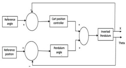
Figure 2. Block Diagram of Inverted Pendulum-cart Controller System
The increase in proportional term increases the speed of response and improves accuracy but the stability deteriorates. The derivative improves the stability of the system and enables increase in gain and decrease in time constant T which increases the speed of the response but i has no impact on steady state accuracy. The steady state errors are reduced using integral term but the speed of response decreases and stability deteriorates. And the derivative term improves the transient response. Thus the PID controller improves both the transient as well as steady state response. For both PID controllers, the standard structure is as follows [1, 6, 12].
PID for angle control:
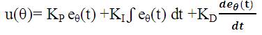
PID for position control:
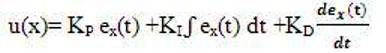
Where,
u is defined as control input
eθ(t) is error in pendulum angle
and ex(t) is the error in position of cart.
PID controller is used for reducing the error between the actual output and the desired output by adjusting the parameters (gains) KP , KI and KD .
Since the two dynamic equations of IP system are coupled to each other (i.e. angle and cart position depends on each other) it makes the tuning of parameters of PID controllers difficult and tedious.
The development of controller for nonlinear inverted pendulum system is not an easy task. Linear controllers don't give satisfactory result. Feedback linearization controller has been developed which reduces the nonlinearities and make the system linear. The following equations form a control law developed for the inverted pendulum system. The equations 14 to 17 are put into the main equation. The main equation (18) calculates the required force, u to keep the pendulum stable.

Here, equation (18) describes the control law.
The parameters and constants are taken as: M=2.4Kg, m=0.23Kg,l=0.36m,g=9.81m/s2,k1 =25, k2 =10,c1 =1, c2 =2.6 [16,17]. Also xd = 0.1 m represents the desired position of the cart and θd =0 rad is the desired upright position of the pendulum rod. A Simulink model of the control law is developed and has been shown in Figure 3.

Figure 3. Simulink Model for Nonlinear Control Law
The MATLAB Simulink model for simulation, analysis and control of the system has been developed. The parameters are taken as [2],
Mass of cart (M)= 2.4kg, mass of pendulum (M)= 0.23kg, length of rod (l)= 0.36m, acceleration due to gravity (g) =9.81m/s2, moment of inertia (I) =0.25kg-m2, length of track L=1m(i.e. ±0.5m) and cart is assumed frictionless.
The Simulink models for PID control and feedback linearization control of IP system has been shown in Figure 4 and Figure 5 respectively. The PID parameters obtained by trial and error are,
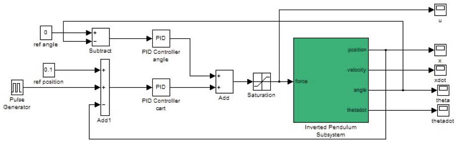
Figure 4.Simulink Model of PID Controller for Inverted Pendulum System
Figure 5. Simulink Model of Feedback Linearization Control for Inverted Pendulum System
For angle PID controller: KP = -40 KI = 0.001 KD = -8 and
For cart PID controller: KP = -1 KI = 0.001 KD = -3
The simulation results are shown in Figure 6 to 10. With PID controller the cart reaches 0.1m and pendulum upright position quickly and smoothly. The control input is bound in the range ± 0.2N. The cart velocity and angular velocity also achieves their desired value with minute error. The feedback controller improves the response by reducing settling time and maximum overshoot for all the output variables and the control input u. With this controller the error is minimized and the speed of the response is increased.
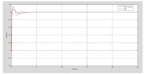
Figure 6. Control Input Response
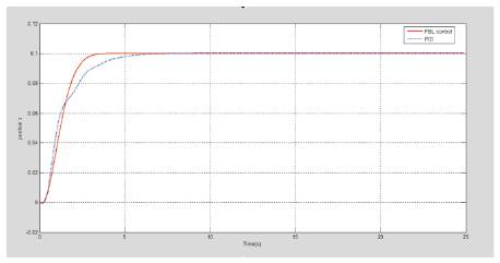
Figure 7. Cart Position Response
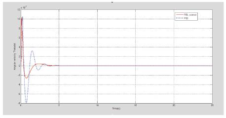
Figure 8. Cart Velocity Response
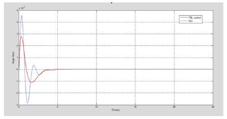
Figure 9. Pendulum Angle Response
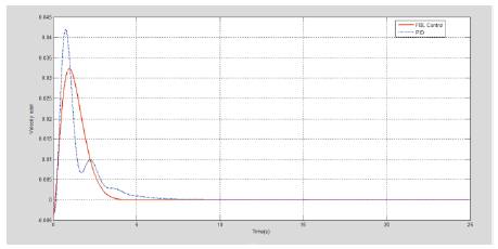
Figure 10. Angular Velocity Response
Feedback linearization and PID control are used to stabilize nonlinear inverted pendulum system, and both the techniques are effective. The system stabilizes satisfactorily with both the controllers. But with feedback linearization control, the cart position approaches nearer to 0.1m (desired position) and the pendulum reaches almost upright position with minor error and faster than the conventional PID controller. Thus the comparative performance analysis justifies that the feedback linearization controller gives more accurate and better result than PID controller.
This paper presents the comparative performance analysis of feedback linearization controller and PID controller for nonlinear inverted pendulum-cart system. Here the objective is to stabilize the unstable and highly nonlinear inverted pendulum-cart system. The feedback linearization control scheme has been implemented to overcome nonlinearities in the system. And to compare the result, the PID control scheme has also been implemented. The simulation results demonstrate the comparative advantage of feedback linearization technique.