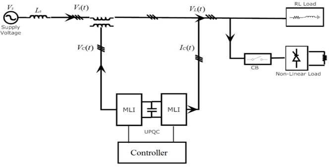
Figure1. Proposed UPQC Configuration
The power quality has become an important issue in recent years. The aim of this paper, is regulation of source voltage at the distribution side under voltage sag as well as harmonics. The Unified Power Quality Conditioner (UPQC) provides combined features of both series and shunt Active Power Filters (APFs). The cascaded multilevel inverter with sinusoidal switching scheme is employed for low Total Hormonic Distortion (THD) in the output. The UPQC controller is designed based on synchronous dq0 transformation. In this paper, the UPQC performance with Proportional Integral (PI) controller and fuzzy logic controllers under sag and harmonics are analyzed in MATLAB environment.
Power quality means maintenance of voltage and current waveforms as sinusoidal with exact phase at constant frequency. There are many power quality issues like voltage sag, swell, harmonics, flickers, transients etc., but voltage sag and harmonics are important power quality issues in recent years [13]. The power electronics equipment is the main source of harmonics. The uses of power electronics devices are very high due to high efficiency and low cost. The faults, sudden injection of inductive load/sudden removal of capacitive load, large variation of On-load Top Changers (OLTCs) of transformer etc., are the sources of voltage sag. The loss of production due to voltage sag is very high in recent years.
In this paper, multilevel configuration of UPQC has been proposed. The cascaded multilevel inverter with sinusoidal switching technique has been considered. The performance of UPQC under voltage sag as well as harmonics has been analysed in later sections.
Unified Power Quality Conditioner is a combination of series and shunt compensators. The series and shunt active power filters are connected via common DC link [1], [2]. The series APF can solve the voltage related problems and shunt APF can solve the current related problems [3]. The series APF is equivalent to controlled voltage source and shunt APF is equivalent to controlled current source. If series APF acts alone, it generates negative voltage harmonics but some of the current harmonics exists. As a result this may not be much capable of current related problems and if the shunt APF alone acts, it generates negative harmonic waveform but some of the voltage harmonics can exist, and this may not be much capable of voltage related problems [2]. The UPQC can mitigate both voltage and current related problems.
There are three main parts in the UPQC structure-they are inverter, controller, energy storage unit (DC source) [4],[5]. Inverter is used to convert DC to AC voltage, controller generates error signals and capacitor acts as a DC source. The regulation of capacitor can be maintained by the shunt APF. If we use capacitor as DC source, then there is only a reactive power exchange between supply and energy source through inverter [6,7,8]. If we use a fixed DC source then there exists only a real power exchange between supply and energy source. The proposed UPQC configuration is shown in Figure 1.
Figure1. Proposed UPQC Configuration
The multilevel inverter offers low THD in the output due to multiple output levels. There are three types of multilevel configurations available, which are diode clamped, flying capacitor and cascaded multilevel inverters [9, 10, 11] . Among those cascaded multilevel inverters are very popular due to circuit flexibility, no need of extra voltage balancing capacitors and clamping diodes and it is best suited for renewable energy sources and low stresses on semiconductor devices. This configuration is best suited for medium voltage applications with minimum devices. The equivalent circuit layout of cascaded Multilevel Inverter (MLI) is shown in Figure 2 [12]. The number of output levels (k) = 2s+1, where s is the number of DC sources or number of H-bridges [13]. The number of H-bridges are added or omitted based on the power requirements. The cascaded MLI output is shown in Figure 3.
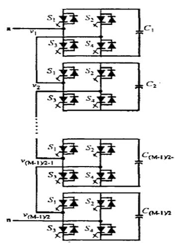
Figure 2. Circuit Configuration of Cascaded MLI
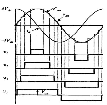
Figure 3. Cascaded MLI Output Waveform
Carrier shifted Sinusoidal Pulse Width Modulation (SPWM) technique is one of the best SPWM technique because of better harmonic elimination in generating pulses to the multilevel inverter. The carriers are shifted by ø=360°s, and here s is the number of H-bridges. The basic generation of pulses by intersection of sine wave (voltage) with triangular carrier is shown in Figure 4.
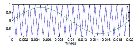
Figure 4. SPWM Switching Scheme
All the pulses are varied in sinusoidal fashion, hence the final output will be stepped waveform with low THD, with the phenomenon of aiding each inverter output, so the resultant waveform has reduced THD due to multiple output states. The output waveforms of cascaded MLI with SPWM scheme is shown in Figure 5.
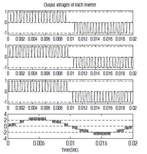
Figure 5. Output Waveforms with SPWM Technique
The UPQC is a combination of series and shunt active power filters. The controllers are separately designed for both series and shunt APFs. The design of filters is based on synchronous dq0 transformation.
1.2.1 Series ControllerThe series controller can mitigate voltage related problems. The compensation of series APF is the difference between source voltage and load voltage (Vse =Vsource –Vload). The design of controller is based on dq0 (synchronous dq0) algorithm. First the source and load voltages Vsabc , Vlabc are transformed into Vdq0 by using parks transformation shown in equations (1), (2). The second order low pass filter (LPF) is used to filter out the higher order harmonics. The designing of series controller is as follows,
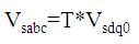
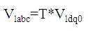
Where,
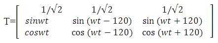
Here T refers to parks transformation matrix. The zero sequence components in both voltages is made to be zero because under unbalanced condition the zero sequence components is not zero which is undesired.
The instantaneous voltages (Vld ,Vlq ,Vsd ,Vsq) are passed through LPF in order to suppress oscillating components and is compared and given in equations (3) and (4).
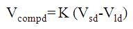
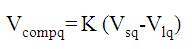
Here K is PI/fuzzy logic controller. The values of Kp, Ki in PI controller are taken based on trial and error method and the fuzzy logic rules are designed in later sections.
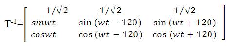
The compensated direct and quadrature axis components are in equations (3), (4) and are converted back to a-b-c quantities by applying inverse parks transformations as shown in equation (5).
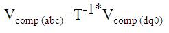
Here T-1 is inverse parks transformation matrix
Where
This compensating voltage in equation (5) is compared with injected voltages and the result is given to SPWM scheme to generate required pulses to operate multilevel inverter.
1.2.2. Shunt ControllerShunt controller can mitigate current harmonics and other related problems which is the basic idea of deriving compensating currents.
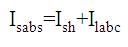
Here Isabc is source current,
Ish is shunt compensator current,
Ilabc is load current.
The mechanism of generation of required compensating currents is same as that of the series controller. The generated compensating current is compared with actual currents and the result is given to SPWM scheme to generate pulses for inverter.
Fuzzy logic is an artificial intelligence technique. Fuzzy logic controllers are very popular due to following reasons.
Figure 6 gives the basic idea of designing Fuzzy Logic Controller (FLC). The basic design of FLC controller is as follows:
FLC has minimum two inputs and one output. Decision making unit selects the appropriate rules from the rule base as given in Table 1. In this paper, triangular membership functions are used in fuzzification process. Centroid method is used in defuzzification process.

Figure 6. Design of Fuzzy Logic Controller

Table 1. Rule Base
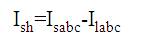
The validation of proposed configuration of UPQC is implemented in MATLAB/SIMULINK software. Voltage sag is created by applying rectifier R-L load using three phase breaker. Due to rectifier load, the harmonics are created and this is the main source of harmonics.
The simulation diagram is shown in Figure 7 and design parameters are given in Table 2.
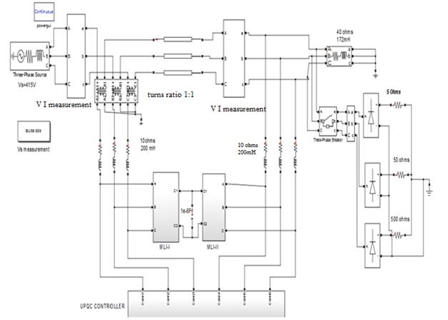
Figure 7. Simulink Model of Proposed System
Table 2. Circuit Parameters of the Proposed System
The simulation results with proposed multilevel UPQC is as follows with PI and Fuzzy logic controllers.
A voltage source of 415V is supplied to the linear load of 100 ohms and 1mH. At the instant of 0.2, an unbalance three phase rectifier load is switched. The proposed control scheme will generate required pulses to multilevel inverters (switching frequency 1080Hz). The source voltage before compensation is given in Figure 8, and after compensation with multi-level UPQC is shown in Figure 9. By observing the results, PI and fuzzy logic controllers are more efficient, but FLC gives better performance. The voltage sag can actively mitigated through both the controllers. The source voltage compensation is shown in Figure 10, and source voltage with PI controller based UPQC is shown in Figure 11. The source voltage with fuzzy based UPQC is shown in Figure 12.
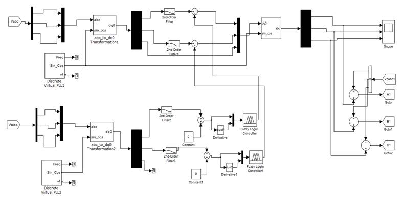
Figure 8. Generation of Pulses for Series APF

Figure 9. Generation of Pulses for Shunt APF
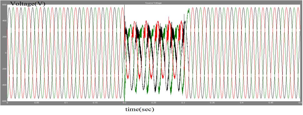
Figure 10. Source Voltage Before Compensation

Figure 11. Source Voltage with PI Controller Based UPQC
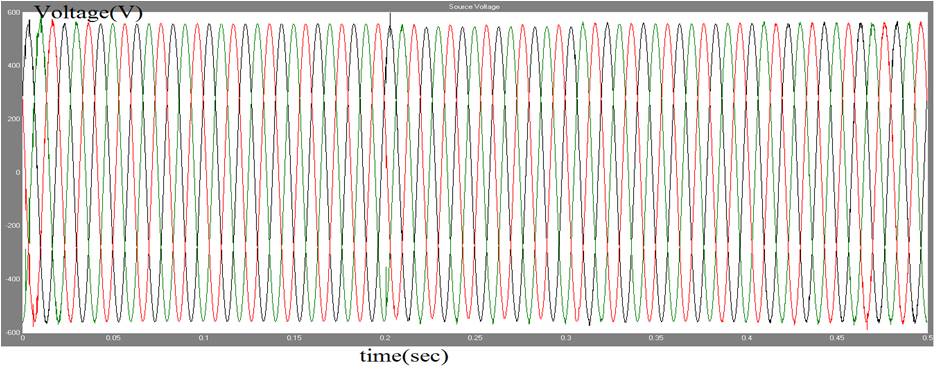
Figure 12. Source Voltage with Fuzzy Based UPQC
The harmonic analysis in the MATLAB can be done using FFT (Fast Fourier Transform) analysis with the help of Powergui block. Figure 13 gives the harmonic analysis of source voltage before compensation, Figure 14 gives the harmonic analysis of source voltage after compensation with PI controller and Figure 15 gives the harmonic analysis of source voltage after compensation with FLC controller. By observing the analysis, PI and fuzzy logic controllers are efficient but FLC controller is better compared to PI controller with appropriate rule base. The designed fuzzy logic controller has 25 rules in rule base. The Syncronous Reference Frame (SRF) theory was implemented using a Fuzzy controller with triangular membership function to obtain the fuzzified input to the controller and the controlled output is defuzzified using Centroid method. The harmonic analysis is listed in Table 3.
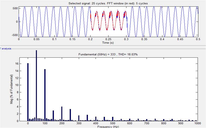
Figure 13. Harmonic Analysis of Source Voltage before Compensation
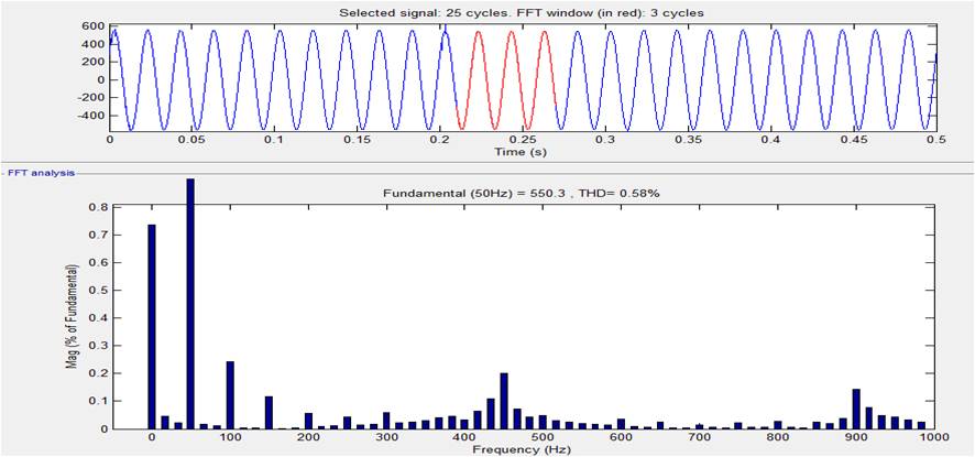
Figure 14. Harmonic Analysis of Source Voltage after Compensation with PI Controller
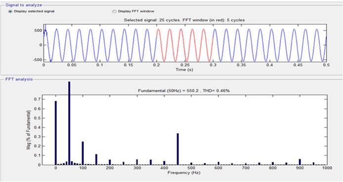
Figure 15. Harmonic Analysis of Source Voltage after Compensation with FLC Controller
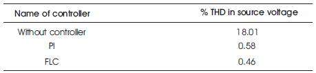
Table 3. Summary of Harmonic Analysis
The designed UPQC system is capable of injecting voltage while compensating for voltage unbalancing and harmonics, under various loads such as the non-linear unbalanced load condition. The source voltages, THD after compensation are well within the IEEE STD. 519 recommended limits.
The multilevel UPQC can actively mitigate various power quality issues. The use of cascaded MLI with SPWM technique gives the low THD in inverter output results with less filter requirements. The UPQC controller with PI controller and FLC with dq0 transformation gives satisfactory results. The voltage sag is mitigated with both PI and fuzzy logic controller. The harmonics in the source voltage reduces from 18.01% to 0.58% with PI controller and 0.46% with fuzzy logic controller.