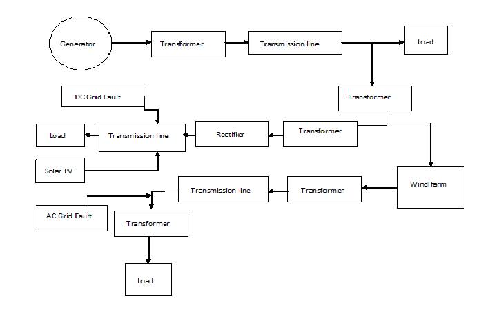
Figure 1. Block Diagram of the Proposed System Conventional Power Grid
With the increase of electricity demand and change of concerning environment, the capabilities of renewable energy generation systems are being expanded. Renewable energy sources are considered as clean and prospective energy sources of the future world. The combination of AC and DC distribution grid is also considered for the efficient connection of renewable power resources. In this case, one of the critical problems due to these integrations is the excessive increase in the fault current. Inorder to protect this smart grid from increasing fault current, a Superconducting Fault Current Limiter (SFCL) could be applied, which has negligible power loss during steady state and capability to limit initial fault currents effectively. This paper research presents, optimal positioning of the SFCL and its effects on reducing fault current in a smartgrid having AC and DC microgrid. The power system was implemented with an AC microgrid having a wind farm with Doubly Fed Induction Generator (DFIG) which is cost effective and improves the power quality, a low voltage DC grid connected with photovoltaic farm. Fault analysis was performed for the symmetrical faults with different SFCL arrangements. The optimal position of SFCL in the smart grid, which could limit fault currents with no negative effect to Distributed Generation (DG) sources and with minimized cost is found to be the integration point of each DG sources in the AC and DC microgrid.
Over the last few years, electrical energy consumption has continually grown and transmission and distribution infrastructure has been more complicated. For such reasons, smart grid concept has been suggested, which could manage the electricity consumption in real time and is more flexible, reliable and responsive than conventional power systems [1]. In a smart grid, transmission and distribution infrastructure will be better to handle possible bidirection energy flows, allowing for distributed generation such as wind turbines, photovoltaic (PV) farms and other power resources. However, one critical problem of these integrations is the excessive increase in a fault current due to the presence of distributed generation within a smart grid [2]. By the multiple routes from power plant to conventional grid, AC and DC microgrid, the excessive fault current in one microgrid could affect the neighbouring microgrid which leads a blackout eventually [3]. Therefore, smart power device which could protect smart grid from the increasing fault current is required for the reliability and the safety of power systems. Inorder to reduce the fault current in smart grid having AC and DC microgrid, SFCL could be applied, which has not only a faster response time to reduce fault current using its quench properties of a superconductor compared to conventional protection devices but also enhance the transient stability of power systems. An SFCL has virtually zero resistance at normal operating condition. But in occasion of a short circuit, due to increasing temperature of the SFCL, the shift from superconducting state to normal conducting state offers maximum preferred impedance to electric networks instantaneously, which limits the current [4-7] In this paper, resistor type SFCL has been modeled [8-10]. Fault analysis was performed for the worst case faults with different SFCL arrangements. From the simulation results, it is possible to determine the strategic installation of SFCLs in power system which limits all abnormal fault currents and has no negative effect on the distributed generation resources [11-14]
MATLAB Simulink/SimPowerSystem was selected to design and implement the SFCL model. A complete smart grid power network including generation, transmission, and distribution with an integrated wind farm and solar photovoltaic farm model was also implemented. Simulink/ Simpower System has number of advantages over its contemporary simulation software (like EMTP, PSPICE) due to its open architecture, a powerful graphical user interface, versatile analysis and graphics tools.
The electric power in the conventional power grid is mainly provided by a 100 MVA conventional power plant having three phase synchronous machine. The power from conventional power plant to the distribution grid is transmitted through 154 kV transmission line having a length of 200 km. For a distribution network, step down transformer (TR2) from154 kV to 22.9 kV is installed in front of the branch networks. The distribution network is divided into three branch networks, conventional power grid, and AC and DC microgrid.
The Figure 1 shows the block diagram of the proposed system with AC and DC microgrid. Each microgrid is integrated with distributed generation sources. AC microgrid has the wind farm which is composed of five Doubly Fed Induction Type wind turbine. Each wind turbine has a 2 MVA rating. The working voltage of AC microgrid is 22.9 kV. In case of DC microgrid, photovoltaic farm of 3kW is connected to the grid.
Figure 1. Block Diagram of the Proposed System Conventional Power Grid
The three phase resistive type SFCL was modeled considering four fundamental parameters of a resistive type SFCL [9]. These parameters and their selected values are:
1) Transition or response time=2msec,
2) Minimum impedance=0.01ohms and maximum impedance = 20 ohms,
3) Triggering current=550A
4) Recovery time=10msec.
Its working voltage is 22.9 kV. Figure 2 shows the SFCL model developed in Simulink/ SimPowerSystem. The SFCL model works as follows. First, SFCL model calculates the Root Main Square (RMS) value of the passing current and then compares it with the characteristic table. Second, if a passing current is larger than the triggering current level, SFCL's resistance increases to maximum impedance level in a predefined response time. Finally, when the current level falls below the triggering current level the system waits until the recovery time and then goes into normal state.
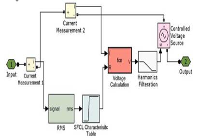
Figure 2. Single Phase SFCL Model Developed in Simulink/ SimPower System
The current limiting resistance value is calculated and this value is implemented in the simulation model. The important parameter to be given in SFCL is the current limiting resistance value. It is stored in the SFCL characteristic table. Inorder to avoid harmonics caused by transients, first order Low Pass Filter (LPF) is used. The SFCL model developed is tested and the current waveforms are recorded with the presence and absence of SFCL.
The fault locations are at the AC grid and DC grid. The SFCL positions are at the substation, branch network and the point of integration of the two sources.
The Figures 3, 4 and 5 show the comparison of fault currents measured at the output of photovoltaic farm. When SFCL is installed at branch network and at the substation, there is no big difference with NO SFCL. But when SFCL is installed at the point of integration of two sources, it limits the fault current instantly without any negative effect because, they are located in direct path of the fault point.
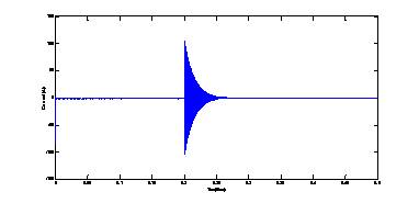
Figure 3. Photovoltaic Farm Fault Current for SFCL at Integration Point
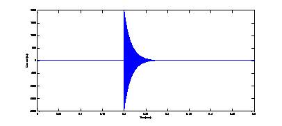
Figure 4. Photovoltaic Farm Fault Current for SFCL at Branch Network
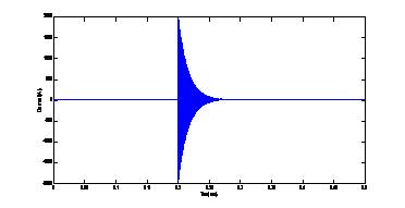
Figure 5. Photovoltaic Farm Fault Current for SFCL at Substation
The above Figures 6, 7 and 8 show the comparison of fault currents measured at the output of wind farm. When fault occurs, there is no big difference with NO SFCL condition. This implies that fault in DC grid is not transferred to the neighbouring AC grid due to the conversion process of the converter station. Therefore, it is considered that the fault in DC microgrid has no influence on the wind farm in AC microgrid.
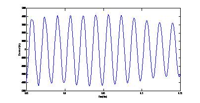
Figure 6. Wind Farm Fault Current for SFCL at Integration Point
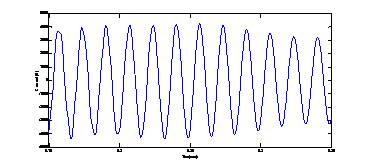
Figure 7. Wind Farm Fault Current for SFCL at Branch Network
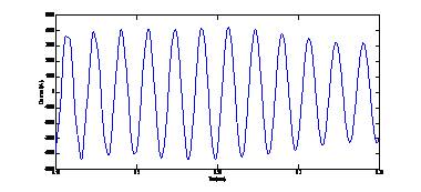
Figure 8. Wind Farm Fault Current for SFCL at Substation
The Figures 9, 10 and 11 shows the comparison of fault currents measured at the output of substation transformer. The fault occurred in DC microgrid has no severe effect on AC grid.
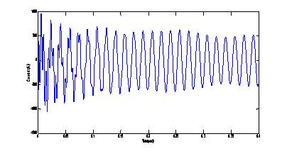
Figure 9. Substation Transformer Fault Current for SFCL at Integration Point
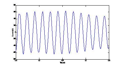
Figure 10. Substation Transformer Fault Current for SFCL at Branch Network
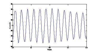
Figure 11. Substation Transformer Fault Current for SFCL at Substation
The above Figures 12, 13 and 14 show when SFCL is installed at the substation or at the branch network, it has no contribution to reduce the fault current but also PV farm contributes to enhance the fault current to neighbouring AC grid. SFCL at the point of integration reduces the fault current and also prevents the contribution of fault current from PV farm to the neighbouring AC microgrid.
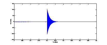
Figure 12. Photovoltaic Farm Fault Current for SFCL at Integration Point
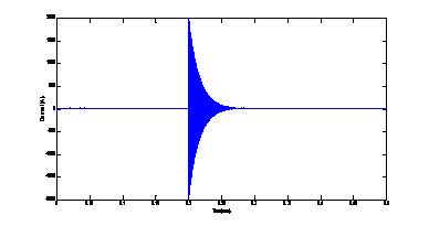
Figure 13. Photovoltaic Farm Fault Current for SFCL at Branch Network
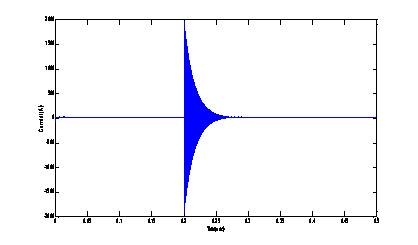
Figure 14. Photovoltaic Farm Fault Current for SFCL at Substation
Figures 15, 16 and 17 show that when SFCL is installed at branch network and at the substation the magnitude of fault current is increased to greater than that of NO SFCL condition. SFCL at the integration point shows better performance in limiting the fault current because it is located in the direct path of fault current occurring in the AC microgrid.
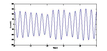
Figure 15. Wind Farm Fault Current for SFCL at Integration Point
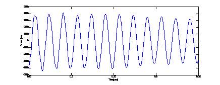
Figure 16. Wind Farm Fault Current for SFCL at Branch Network
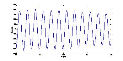
Figure 17. Wind Farm Fault Current for SFCL at Substation
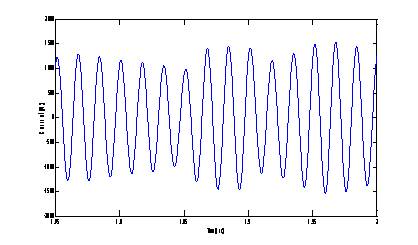
Figure 18. Substation Transformer Fault Current for SFCL at Integration Point
Figures 18, 19 and 20 show that the fault currents are reduced for all SFCL arrangements except for SFCL at branch network and at the substation.
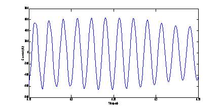
Figure 19. Substation Transformer Fault Current for SFCL at Branch Network
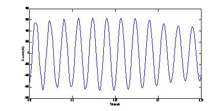
Figure 20. Substation Transformer Fault Current for SFCL at Substation
Table 1 and Table 2 show the effect of SFCL in AC and DC grid. Table 3 shows the optimal positioning of SFCL in AC and DC grid.
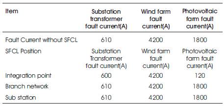
Table 1. Positioning of SFCL for DC Microgrid
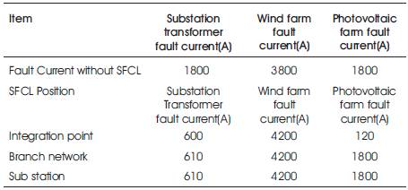
Table 2. Positioning of SFCL for AC microgrid
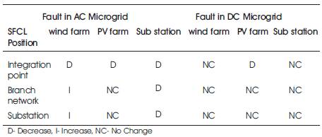
Table 3. Effective Positioning of SFCL in AC and DC Microgrid
This research paper presents feasibility analysis results of positioning of the SFCL and its effects on reducing fault current in smart grid having AC and DC microgrid together. From the simulation results, the optimal location of SFCLs in power systems, which limits all abnormal fault currents and has no negative effect on the distributed generation resources, has been proposed. SFCLs installed at the integration point of two sources shows the best fault current limiting performance because they are located in the direct path of the fault current occurring in AC and DC microgrid.