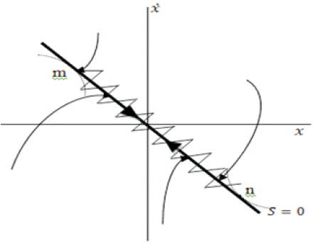
Figure 1. Sliding Surface
In this paper, the authors have aimed to develop a control technique using Sliding Mode Control (SMC) and Dynamic Sliding Mode Control (DSMC) for a pH control plant. This pH plant is also subjected to a Proportional Integral Derivative (PID) controller. The pH control process involves a prototype model in which acidic and alkaline streams are mixed into a Continuous Stirred Tank Reactor [CSTR] in proper proportions to control the pH of the plant. The control mechanism involves control of the flow rate of the acid and alkaline solutions. SMC and DSMC are the types of Variable Structure Control (VSC). As the neutralization process is non linear, VSC serves as a better solution. Also PID control is implemented on this process and the results are compared. The unique feature of this paper is that all the control methods are implemented using LabVIEW software. LabVIEW stands for Laboratory Virtual Instrumentation Workbench. The programming is done with this software and is applied to the prototype model. The results of PID, SMC and DSMC are compared and it is found that VSC controllers are better suited than PID controllers.
Wastewater from metal finishing industries contains contaminants such as heavy metals, organic substances, cyanides and suspended solids at levels which are hazardous to the environment and pose potential health risks to the public. The techniques used in the conventional treatment of wastewater involve precipitation of heavy metals, flocculation, settling and discharge. The treatment requires adjustment of pH as well as addition of chemicals. pH is monitored and controlled by manipulating an acid and a base stream. Modern treatment plants involve physical and chemical precipitations where maintenance of pH is the key factor for efficient treatment. Most of the processes use a pH sensor as the online measuring control. In this paper, LabVIEW technique is used to operate and control the system automatically by online digital computer. It was found that pH control in a wastewater treatment process [1] is very difficult and the difficulties arise from severe process nonlinearity and frequent load changes [2]. The S – shaped titration curve is the primary source of the non-linearity. A possible better solution for better control of pH in wastewater treatment process is aimed at in this paper by using VSC. Some studies have been done in the non linear control area which indicates the robustness of VSC [3].
Sliding Mode Control (SMC) is a type of Variable Structure Control (VSC). In control theory, SMC is a nonlinear control method that alters the dynamics of a nonlinear system by the application of a discontinuous control signal that forces the system to "slide" along a cross-section of the system's normal behavior [4]. The state-feedback control law is not a continuous function of time. Still it can switch from one continuous structure to another continuous structure depending on the present position in the state space. Hence, sliding mode control is a type of variable structure control method [5]. The multiple control structures are designed so that the trajectories always move toward an adjacent region with a different control structure, and so the ultimate trajectory will not exist entirely within one control structure. Instead, it will slide along the boundaries of the control structures. The motion of the system as it slides along these boundaries is called a sliding mode. This geometrical locus consisting of the sliding mode boundaries is called the sliding (hyper) surface. In the context of modern control theory, any variable structure system, like a system under SMC, may be viewed as a special case of a hybrid dynamic system as the system flows both through a continuous state space but also moves through different discrete control modes.
Figure 1 shows an example trajectory of a system under sliding mode control. The sliding surface is described by s=0, and the sliding mode along the surface commences after the finite time when system trajectories have reached the surface. In the theoretical description of sliding modes, the system stays confined to the sliding surface and need only be viewed as sliding along the surface. However, real implementations of sliding mode control approximate this theoretical behavior with a high frequency and generally nondeterministic switching control signal that causes the system to chatter in a tight neighborhood of the sliding surface [6]. This chattering behavior is evident in Figure 1, which chatters along the s=0 surface as the system asymptotically approaches the origin, [7] which is an asymptotically stable equilibrium of the system when confined to the sliding surface. In fact, although the system is nonlinear in general, the idealized (i.e., non-chattering) behavior of the system in Figure 1 when confined to the s=0 surface is a Linear Time Inveient (LTI) system with an exponentially stable origin.
Figure 1. Sliding Surface
Sliding mode control uses practically infinite gain to force the trajectories of a dynamic system to slide along the restricted sliding mode subspace [8]. Trajectories from this reduced-order sliding mode have desirable properties (e.g., the system naturally slides along it until it comes to rest at a desired equilibrium). The main strength of sliding mode control is its robustness. Because the control can be as simple as a switching between two states (e.g., "on"/"off" or "forward"/"reverse"), it need not be precise and will not be sensitive to parameter variations that enter into the control channel. Additionally, the control law is not a continuous function, the sliding mode can be reached in finite time (i.e., better than asymptotic behavior). Under certain common conditions, optimality requires the use of bang–bang control; hence, sliding mode control describes the optimal controller for a broad set of dynamic systems. One application of sliding mode controller is the control of electric drives operated by switching power converters. Sliding mode control has many applications in robotics. In particular, this control algorithm has been used for tracking control of unmanned surface vessels in simulated rough seas with high degree of success. Sliding mode control must be applied with more care than other forms of nonlinear control that have more moderate control action. In particular, the actuators have delays and other imperfections, so the hard sliding-mode-control action can lead to chatter, energy loss, plant damage, and excitation of un-modeled dynamics. Continuous control design methods are not as susceptible to these problems and can be made to mimic sliding-mode controllers.
The process consists of three chemical containers (cylindrical type) with size 5 litres each. These containers contain an acid (Hcl), a base (NaOH) and the sample liquid whose pH has to be neutralized. They are made of resist glass antichemical corrosion material. Another tank is used for mixing the above solutions at proper rate. This vessel is called mixing tank. It also contains a fiber glass stirrer which is used to stir the liquid at proper intervals. The capacity of this tank is also 5 litres. An additional reservoir tank (cylindrical type) is also present which serves as a reservoir whose capacity is 10 litres. Figure 2 shows the block diagram of the process.
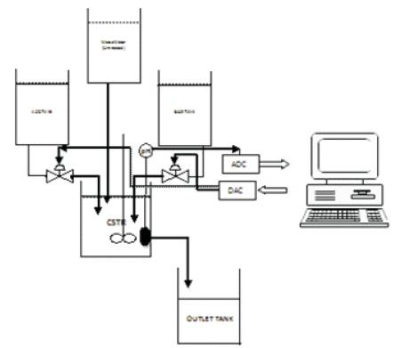
Figure 2. Block Diagram of the Process
A permanent magnet DC Motor with ratings of 12 V DC, 1500 RPM, torque 1kg-cm is use for stirring. An RTD for this is provided for temperature compensation. Piping and manual valves and fittings with sizes from 1/8 to 1/4 inches were made of polyethylene plastic which resist the chemical corrosion. Nylon tubing is provided for pneumatic pressure transfer. pH measuring sensor uses glass electrode. Two control valves (Equal Percentage type) with 2-way operation which are of normally closed type are used for acid and base flow respectively. The input signals are 3-15 psi. Both have ½ inch body with 1/4 inch trim. The body of acid valve is made of Teflon to prevent corrosion. Two current to pressure converters are used which provides an output ranging from 3 to 15 psi. A PC is used to run the LabVIEW software and control the whole process.
Before starting, the system is always cleaned from any contaminated material. The pH sensor is calibrated by standard solutions. The experimental runs are achieved by on-line digital computer. The tanks are to be filled with the respective reagents. The interfacing between the plant and the computer are to be verified. The power supplies to the various units are established to be proper and power supply is switched on. The required pH in the tank is to be set and the controller is to be selected from the LabVIEW interface. The process variable (pH in the tank) is sent to the computer through the NI-DAQ input module (in the form of a current signal varying between 4-20mA) and the program generates an error signal depending on the value of the variable. The controller is given the error signal and manipulates it accordingly and generates a control output. The control output is given to the current to pressure converter through the NI-DAQ output module (in the form of a current signal varying between 4-20mA). The current-to pressure converter generates a corresponding pressure depending upon the input current received. The pressure from the current to pressure converter is in the range of (3- 15) psi. The pressure is used to regulate the positioner of the acid and base valves. The acid or base valves are thus opened or closed and the pH in the tank is regulated. The outputs are observed in graphical format on the computer and can be exported to Microsoft Excel to obtain values in tabular format.
Process control is an engineering discipline that deals with architectures, mechanisms and algorithms for maintaining the output of a specific process within a desired range. Process control is extensively used in industry and enables mass production of consistent products from continuously operated processes such as oil refining, paper manufacturing, chemicals, power plants and many others.
A proportional Integral Derivative Controller (PID controller) is a control loop feedback mechanism (controller) widely used in industrial control systems. A PID controller calculates an error value as the difference between a measured process variable and a desired set point. The controller attempts to minimize the error by adjusting the process through use of a manipulated variable.
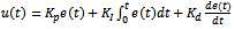
Where,
Kp is the proportional gain
Ki is the Integral gain
Kd is the Derivative gain
The equation (1) gives the overall controller action for the PID controller. It is the sum of Proportional, Integral and Derivative actions of the error signal.
The Sliding Mode Control (SMC) is a type of Variable Structure Control. It has high insensitivity to disturbances and parameter variations. SMC can be divided into two parts:
(1) The design of a stable sliding surface and
(2) The design of a control law to force the system states onto the chosen surface in finite time.
The design of the surface should address all constraints and required specifications. A sliding mode controller is a nonlinear control method that alters the dynamics of a nonlinear system by application of a discontinuous control signal that forces the system to slide along a cross-section of the system's normal behavior.
SMC uses practically infinite gain to force the trajectories of a dynamic system to slide along the restricted sliding mode subspace. Trajectories from this reduced-order sliding mode have desirable properties. The main strength of sliding mode control is its robustness. As actuators have delays and other imperfections, the hard sliding-modecontrol action can lead to chatter, energy loss, plant damage, and excitation of un-modelled dynamics. The control action in this project is a simple action of switching between two states; it will be less sensitive to parameter variations. The control law is a discontinuous function and so the sliding mode can be reached in finite time. The design of Static Sliding Mode Controller is done by first defining the sliding surface. The Sliding Surface is defined as
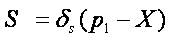
where,
δs is a positive scalar.
δs defines the slope of the sliding surface.
X is the desired pH which is a constant
p1 is the actual pH of the system.
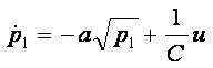
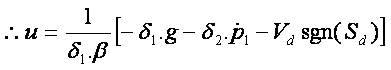
The control law to drive the system to the sliding surface is given by,
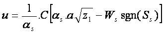
The system shows a chattering effect at the output. This is due to the discontinuous control effect of the shift in trajectories. To minimize this effect a Dynamic Sliding Mode Control is applied. This decreases the chattering and limits it thereby giving a smooth output.
The Dynamic Sliding Mode Control (DSMC) is another type of Variable Structure Control. In the response of the sliding mode controller it can be seen that it is heavily affected by chattering. Chattering is an unwanted phenomenon occurring in the output which creates continuous ON/OFF movements in the final control element. To overcome this disadvantage DSMC is applied. The design of Dynamic Sliding Mode Controller is done by first defining the sliding surface. Here, δ1, δ2 and Vd are positive scalars. X is the set height which is a constant. The dynamic controller is driven by the output to introduce additional dynamics and increase the degree of freedom.
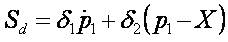
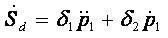
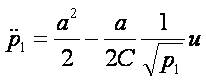
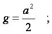
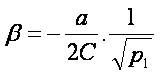
The dynamic modeling of system and its control law is as follows.
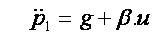
where,

The experimental apparatus designed for this project is a reactor of 5 litre capacity and pH and flow sensors coupled with a control and monitoring unit. The pH sensor is a glass electrode and has a temperature compensation system provided. The reactor operates at atmospheric pressure and temperature and is stirred at around 1000 rpm. The reactor is fed with three inlet streams provided with pumps. The acid stream is 0.1 M HCl and the base stream is 0.1 M NaOH. The reactor behaves as a continuous stirred tank reactor. Both the acid and the base streams are manipulated to achieve the desired pH level in the tank. The interfacing with the laptop is performed using data acquisition cards provided by National Instruments, Texas. The controllers are designed in the LabVIEW software environment. The data is transmitted to the virtual instrument and the virtual instrument is executed and the amount of acid and/or base to be added is computed and the control valves are manipulated accordingly. Figure 3 shows the experimental setup of the process. The figure shows the two tanks which contains Acid and base solutions. The tank located in the centre contains the waste water whose pH has to be regulated. It also indicates the Continuous Stirred Tank Reactor [CSTR] which is used to regulate the pH by mixing the acid and base solutions.

Figure 3. Experimental Setup of the Process
The virtual instruments simulating the various control actions is as follows. Figure 4 shows the front panel of the whole process. It indicates the controllable features of the system. It allows the change of Ph of the system. The design of the front panel has to be done in such a way that it enables the user to use the controls in a familiar method. It consists of knobs, dials and also graphically represented tanks with graduations.
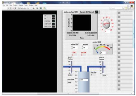
Figure 4. Front Panel of the Process
The plant was cleaned to remove contamination and the pH sensor was calibrated using standard solutions. The tanks are filled with the respective reagents – HCl in the acid tank and NaOH in the base tank. The interfacing between the plant and the computer was verified and the desired pH level was selected from the LabVIEW interface. The outputs were then observed in the graphical format. To obtain the exact values at every instant, the graphs were exported to Microsoft Excel and the values were obtained as a variation of time in a tabular format. The desired set point to be maintained in the tank was selected as 13. The following graphs were obtained after the controllers were applied for the process.
The set point was set at pH level 13. The pH level attained set point after 28 seconds. The overshoot observed was around ±0.2 pH. Figure 5 indicates the result obtained after applying PID controller. The values of the gain constants used in equation 1 are obtained using tuning techniques. Zeigler nichols method is used and the following values are obtained.
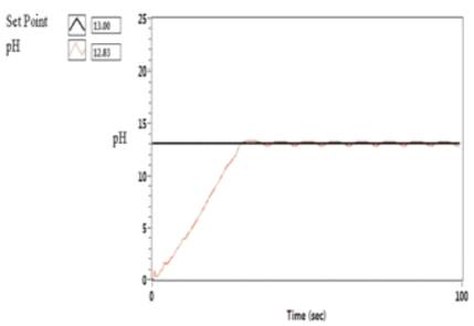
Figure 5. Graph Showing the Variation of pH in the Tank
Kp = 2.1
Ki =0.042
Kd =0.63
The set point was set at pH level 13. The pH level attained set point after 30 seconds. The overshoot observed was around ±0.2 pH. Figure 6 indicates the resultant waveform of the system after the application of Sliding Mode Control. The Figure 7 shows the flow of acid and base into the tank. It is seen that a lot of chattering is observed. To minimize this effect a Dynamic Sliding Mode (DSM) can be incorporated.
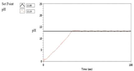
Figure 6. Graph Showing the Variation of pH in the Tank
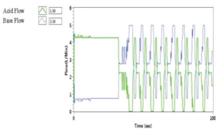
Figure 7. Graph Showing the Acid and Base Flows in the Tank
The set point was set at pH level 13. The pH level attained set point after 22 seconds. The overshoot observed was around ±0.1 pH. Figure 8 indicates the resultant waveform of the system after the application of Dynamic Sliding Mode Control.
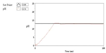
Figure 8 Graph Showing the Variation of pH in the Tank Due to Dynamic Sliding Mode Controller
The Figure 9 shows the flow of acid and base into the tank. It is seen that the earlier chattering is reduced. This increases the life span of the final control elements i.e, Control Valves.
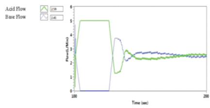
Figure 9. Graph Showing the Acid and Base Flows in the Tank
Few researches have been done earlier in this neutralization process [9]. But this research paper is unique in incorporating the whole system control using LabVIEW software. This paper presents PID, Sliding Mode and Dynamic Sliding Mode control for a pH neutralization pilot plant. Process modeling approach adopted in this paper is based on the Physico-chemical principles and fundamental laws. A conventional mathematical modeling process is incorporated. Practical tests are carried out on actual system to estimate manipulating variables which were not known before experiments. The sliding mode controller increased the robustness of the system under study and the changes in real time were incorporated satisfactorily. The chattering features of the output are overcome by incorporating a Dynamic mode controller.