[1]

Under partial shading conditions, multiple peaks are observed in the power-voltage (P-V) characteristics curve of a photovoltaic (PV) array, and conventional maximum power point tracking (MPPT) algorithm may fail to track the global maximum power point (GMPP). In this paper a fuzzy-logic controller for global maximum power point tracking (GMPPT) is proposed to increase the performance during partial shading condition. A mathematical model of the PV system under partial shading conditions is derived. The proposed fuzzy logic based controller is implemented in MATLAB- SIMULINK.
Photovoltaic (PV) systems have huge market and research interests recently due to their noiseless and environmental friendly power-generating process [1-3]. Power generated by PV modules depend upon solar irradiation level. A maximum power point tracking (MPPT) controller is required to ensure that highest possible power is generated. In order to achieve maximum power point tracking (MPPT), many MPPT methods have been developed and implemented in previous studies such as Perturb and Observe (P & O), incremental conductance, fractional open-circuit voltage, fractional short-circuit current , line approximation, and ripple correlation control (RCC). These techniques have high tracking accuracy under steady weather conditions. During partially shaded conditions, the system PV characteristic curve has multiple peaks. Therefore, a convention maximum power (MPP) tracker (MPPT) could miss the global maximum point [4-6].
A study of partial shading condition in [7] shows that using of conventional MPPT during partial shading could result in significant power loss from the PV array.
The application of global MPPT algorithm [8] requires the characterization of the PV source after each partial shading topology has been established. In [9], the global MPP is tracked by scanning the P-V curve based on information of the PV module open-circuit voltage and their configuration on the PV array. The global MPPT methods presented in [10] and [11] are based on the measurement of the PV array open-circuit voltage and solar irradiation or short-circuit current respectively. A common drawback of these methods is that they require knowledge of the electrical characteristics of PV modules and/or their configuration within the PV array.
[12] Proposes a short-circuit pulse based MPPT with fast scan on the P-V curve to identify the proportional parameters which is commonly used in a current-based MPPT [13]. The global maximum power point is found: however, an additional switch in parallel with the PV source is required to compute short-circuit current every few minutes. Therefore, such a method causes momentary power losses and requires additional cost. To avoid extra switch, the authors in [14] propose a controller that swings the converter's duty cycle from zero to one step to the optimal operating point. The conventional hill climbing algorithm is used to maintain operation around the maximum point. Local maxima are avoided; however, significant loss in power is experienced during the computation of the open-circuit voltage and short-circuits current. A two-stage MPPT using monitoring cells is presented in [15], where the operating point in the first stage move to the MPP by assuming that the P-V curves is uniform. In the second stage, the increment resistor method is used to locate the real MPP. It would overlook the global MPP in some partial shading conditions, and also, open-circuit voltage and short-circuit current measurements are required.
In this paper, a fuzzy-logic based hill climbing technique is proposed to track the global maximum point in nonuniform P-V curve characteristics. The proposed technique identifies the global maximum among any number of local maxima. Unlike conventional MPPT where the PV system operating power is perturbed and observed to track the MPP , the proposed controller scans and stores the maximum power during the perturbation and observation stages, moreover, PV modelling during partial shading conditions is also proposed.
A PV system of a solar array is a group of series/parallel connected modules, where basic building block within the module is a solar cell. Commercially used solar cells rated ‘A’ varies between 1 W and 2 W depending on the material and the surface area. The PV array is shown in Figure1.
The basic characteristics of the solar cell are non-linear due to operational physical phenomena. The equivalent circuit of the solar cell is shown in Figure 2,
The mathematical model of the PV system is represented by


Where,
Vpv and IPV represent the array output voltage and current, respectively
Rs and Rsh are solar cell series and shunt resistances,
A is a junction material constant
k is Boltzmann's constant (1.38 X 10⁻²³ J/K)
np and ns are the numbers of cells connected in parallel and series respectively.
Io is the reverse saturation current of the diode,'A'
Irs is the reverse saturation current of the diode
Top and Tr are operating and reference temperatures in K
q is the charge of electron 1.6X10⁻¹⁹ C
Isc is the short circuit current of the PV cell, ‘A’
Ki the constant of temperature coefficient
Eg is the energy band gap which is 1.2 ev
Voc is the open circuit voltage of the PV cell, ‘V’
The characteristic curves of the PV array system depend on the radiation and temperature of the PV system. Here in this paper the authors have designed a PV array and the different irradiations and temperature variations observed are shown in Figure 3.
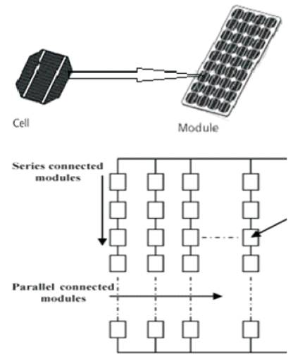
Figure 1. PV Array System
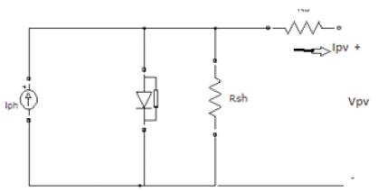
Figure 2. Equivalent circuit of a PV cell
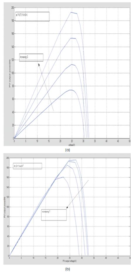
Figure 3. Influence of (a) temperature (T) and (b) solar irradiation (G) on the P-V characteristics
The P-V characteristics show the variation of power with respect to irradiation and temperature.
To study the effect of partial shading in this paper, the authors would like to consider the array as shown in Figure 4.
In order to study the effect of non-uniform shading, different possible combinations of radiations are considered.
Case1 one module in each column is completely shaded (viz., modules 1, 4, and 7).
Case2 one module in each column is partially shaded with equal radiation levels (viz., modules 2, 5, and 8)
Case3 one module in each column is partially shaded with unequal radiation levels (viz., modules 3, 6, and 9).
Case 4 two modules in the first column and one module in each other column are partially shaded with equal radiation levels (viz., 1, 2, 4, and 7).
Case 5 all the modules are partially shaded with different radiation levels.
The simulation results for the five cases are shown in Figure 5.
The simulation results indicate that a completely shaded module causes a reduction of the PV output power without creating local maxima.
However, partially shaded modules result in the reduction in of the PV output power, creating local maxima, where the number of local maxima increases as the variation of each module increases.
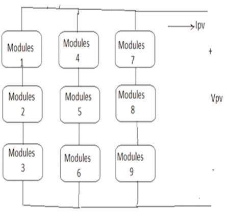
Figure 4. PV array system with nine modules connected in series and parallel
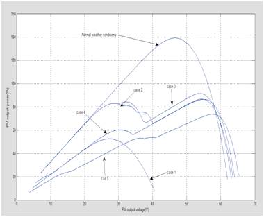
Figure 5. PV output power characteristics under five cases
From the above simulation results, we come to know that the basic solar cell equations won't satisfy under partial shading conditions. So we need to model a mathematical modelling under partial shading conditions.
For that a simple case as series-connected PV modules is considered. Here in this paper, the data for the shell SP150- PC , the short circuit current and the open-circuit voltage for each PV module under rated radiation level are 4.4 A and 43.4 V respectively.
Where
Isc = short-circuit current of the unshaded PV modules
Istep =short circuit current of the shaded PV module

Vstep = summation of the open-circuit voltages of the unshaded modules.
Voc = summation of the open-circuit voltages of the shaded and unshaded modules.
Here understanding the mathematical simulation is done by considering three modules in series as shown in Figure 6 (a). From the V-I characteristics (Figure 6b) we come to know the relationship between output voltage by considering one module shaded with 500 W/m2 and remaining two with 1000 W/m2 .
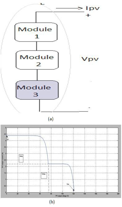
Figure 6 (a) Block diagram of three series connected PV module system(b) Characteristic curve of the PV output current and voltage
Further investigation is done by shading another module as shown in Figure 7 (a). Here Two modules are shaded with 500 and 300 W/m2 . From the V-I characteristics (Figure 7b) the expression for the output voltage of the array is used.
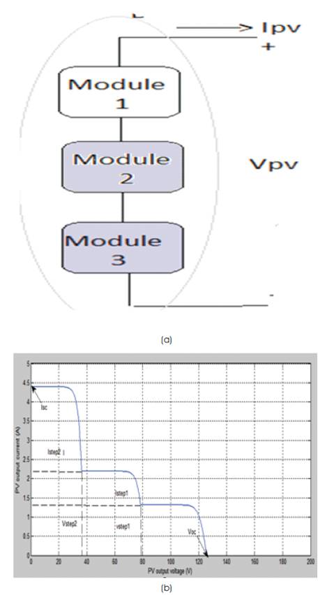
Figure 7 (a) Block diagram of three series connected PV module system (b) Characteristic curve of the PV output current and voltage
In order to know the effect of connecting parallel branch, we must know what is the effect of a parallel branch under partial shading conditions. It is observed by connecting the modules as shown in Figure 8 (a) and the output V-I characteristics are shown in Figure 8 (b).
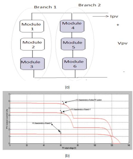
Figure 8.(a) Block diagram of the series/parallel connected PV module system(b) Characteristics curve of the PV output current and voltage
In the first branch, modules 1 and 2 receive a radiation of 1000 W/m2 and shaded module receives 500 W/m2. The three PV modules in the second branch are partially shaded to receive a radiation of 300 W/m2.

The general mathematical model of N parallel connected PV modules in the PV system is


Unlike conventional MPPTs, where the PV system operating power is perturbed and observed to track the MPP, scanning, storing, perturbing, and observing the operating power of the PV system are used for the proposed MPPT. The proposed method is able to track the MPP under any weather conditions, particularly partial shadowing where local and global maximum points exist. During the initial condition or varying weather conditions, the proposed MPPT makes a wide range search to scan and store the maximum power value on the PV system. A pre-set value which represents the accepted difference between the identified maximum power and the operated power is stored to decide the controller rules. If the difference between the identified maximum power and the operated power is greater than the pre-set value, the duty cycle is increased; otherwise, fuzzy-logic-based MPPT is applied.
Figure 9 shows the flowchart of the proposed method, where Vpv and I are the PV output voltage and current, respectively, D is the duty cycle, Ppv is the global MPP, and ΔP is a constant that identifies the allowable difference between the global maximum point and the operating power point. Figure 10 shows the PV Array System Block Diagram and proposed MPPT controller
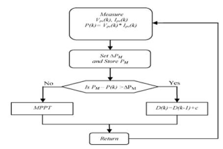
Figure 9. Flow chart of proposed method
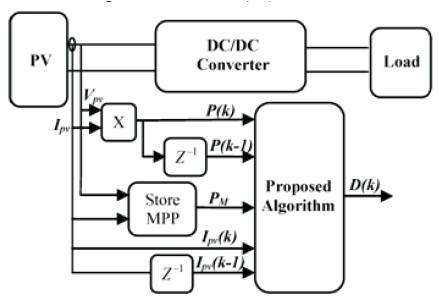
Figure 10. PV Array System Block Diagram and proposed MPPT controller
FLC Design


And the output equation is

Where ΔP and ΔI are the PV array output power change and current change, respectively, ΔP is the difference between the stored global maximum power (PM) and the current power, and ΔD is the boost converter duty cycle change.
The variable inputs ΔP and ΔI are divided into four fuzzy subsets: positive big (PB), positive small (PS), negative big (NB), and negative small (NS). The variable input ΔPM is divided into two fuzzy subsets: PB and PS. The output variable ΔD is divided into six fuzzy subsets: PB, positive medium (PM), PS, NB, negative medium (NM), and NS.
Therefore, the fuzzy algorithm requires 32 fuzzy control rules [16].
The last fuzzy controller stage is defuzzification where the Center-of-the-area algorithm is used to convert the fuzzy subset duty cycle changes to real numbers.

The tested PV array is composed of ten series modules with array rated power of 850 W, where the design specification and circuit parameters are shown in Table 2.
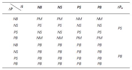
Table 1. Fuzzy-Logic Rules
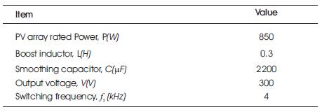
Table 2. Design Specifications And Circuit
The proposed system is tested under two equally distributed radiation levels: 500 and 1000 W/m2. As shown in Figure 11, the global maximum scan causes some power loss during initial and varying weather conditions. Nevertheless, the proposed MPPT still attains the MPP in a relatively short time, with small oscillation in steady state.
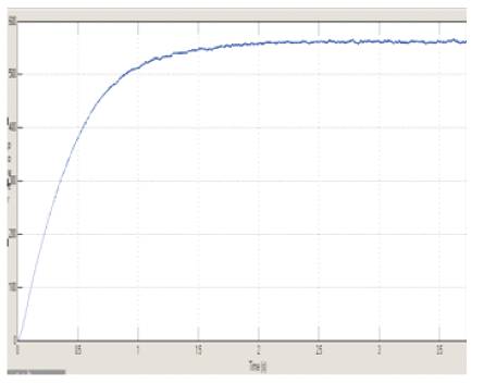
Figure 11. MPPT Technique under normal weather conditions
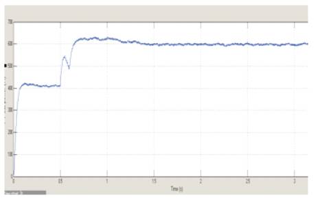
Figure 12. PV output power for the proposed MPPT under partially shaded conditions
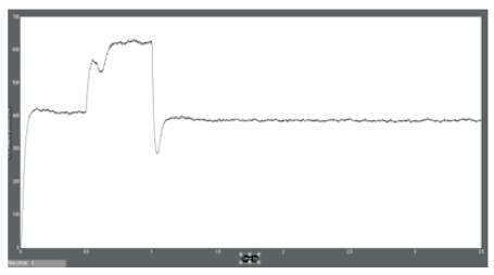
Figure 13. Output power for a partially shaded PV system under two radiation levels
To validate the performance of the proposed MPPT during partial shading, the PV system is tested under different distributed radiation levels.
In this paper, a fuzzy-logic-based MPPT has been proposed to extract the global MPP under partially shaded PV system conditions. The proposed MPPT has been implemented by combining fuzzy-logic-based MPPT with a scanning and storing system. A new mathematical model has been proposed to represent the behaviour of the P-V characteristic under partial shadowing conditions.