Figure1. Block diagram of Development of Robotic Arm
This thesis deals with the creation of a device that will climb towering palms to harvest (primarily) coconuts. It will foster not only a love for engineering, designing, and inventing, but also a feeling of pride and accomplishment in helping people who live in coconut-harvesting countries. There are no 100% safe coconut-harvesting devices currently in the market. Although there have been efforts made by many inventors, the most similar contraption is a coconut-climbing assistance device that assures efficiency, but not necessarily safety. The proposed coconut-climbing device will attempt to address both efficiency and safety. The design of the device has to be simple and enough for villagers to operate, yet work efficiently to appeal to the majority. Other design obstacles include creating a multi-axis arm, allowing the villagers to observe what is happening at the top of the tree, and maintaining the friction between the device and the tree when the device ascends and descends. A coconut plucking robot is created in hopes of saving lives and improving the living standards of many coconut-climbers.
In scientific mind, the coconuts are known to belong to the “arecacea” family, also known as the palm family, which is comprised of about 200 genera and 2,500 species. Palms range from tiny plants to towering trees reaching over forty meters (over 120 feet), and are found throughout the tropics and subtropics. Commercially important palms include coconuts, dates, oil palms, with over five billion coconuts harvested every year, and coconuts play a huge role in the economy of several regions and countries. Prominent places of harvest of coconuts are the Indian states of Tamil Nadu, Kerala and Karnataka, the Lakshadweep Islands, the Andaman Islands, Caribbean countries, Australia–Oceania Countries and many African and South American countries. The majority of coconuts are harvested by climbing the tree and cutting the nuts down by hand. This process may seem to be simple, however, it is actually quite dangerous. In response, there is a genuine need to develop a device, i.e. robotics, A reprogrammable, multifunctional manipulator designed to move material, parts, tools, or specialized devices through various programmed motions for the performance of a variety of tasks, and an automatic device that performs the functions normally ascribed to humans or a machine in the form of a human.
Robotics develop man-made mechanical devices that can move by themselves, whose motion must be modeled, planned, sensed, actuated and controlled, and whose motion behavior can be influenced by “programming” [1, 2]. Robots are called “intelligent” if they succeed in moving in a safe interaction with an unstructured environment, while autonomously achieving their specified tasks.
This definition implies that a device can only be called a robot if it contains a movable mechanism, influenced by sensing, planning, and actuation and control components. It does not imply that a minimum number of these components must be implemented in a software, or be changeable by the consumer who uses the device [4] for example, the motion behavior can be hard-wired into the device by the manufacturer.
The presented definition covers not just pure robotics or only intelligent robots, but rather the somewhat broader domain of robotics and automation. This includes “dumb” robots such as: metal and woodworking machines, intelligent washing machines, dish washers and pool cleaning robots etc. These examples all have sensing, planning and control, but often not in individually separated components.
Robotics is, to a very large extent, all about system integration, achieving a task by an actuated mechanical device, via an intelligent integration of components, many of which it shares with other domains, such as systems and control, computer science, character animation, machine design, computer vision, artificial intelligence, cognitive science, biomechanics [3]. In addition, the boundaries of robotics cannot be clearly defined, since also its core ideas, concepts and algorithms are being applied in an ever increasing number of “external” applications, and, vice versa, core technology from other domains (for example vision, biology, cognitive science or biomechanics,) are becoming crucial components in more and more modern robotic systems.
This project has a unique feature that it is controlled from cell phone. All its the movements are controlled from any cell phone. That means that we can control this robot from anywhere in the world where GSM / CDMA network service is available. The robot has built in GSM / CDMA cell phone that receives signals from other cell phones. One has to call the number of the cell phone (that is inside robot) from his cell phone to activate it. Then by pressing different keys from 0 - 9 form the phone he can control the movements of the robot. Its 4-axis robotic arm, and it's all four motions are controlled by 2 DC gear motors and 2 servo motors.
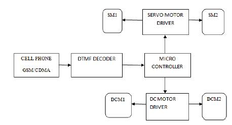
The major building blocks are cell phone, DTMF decoder, micro-controller, DC motor and Servo motor driver circuits.
Figure 1 shows the block diagram of the development of Robotic Arm.
Figure1. Block diagram of Development of Robotic Arm
This is very first and the most important part of the system because due to this only the entire system is activated and works. It will receive the signals from another cell phone and gives them as input to DTMF decoder. First the system is activated by calling the SIM card number inside the phone. Afterwards it will receive DTMF code signals dialed from another cell phone and give it to DTMF decoder.
The function of this block is self understood. It will take the DTMF input given by cell phone, decode it and gives 4-bit digital output to micro controller. It also generates an interrupt every time when it gives digital output.
This block is the heart of entire system because it actually performs all the controlling actions. When this block is called depending upon the code given by DTMF decoder, it will perform the following tasks.
It receives actuating signals from micro controller in terms of high / low logic, and amplifies (current) it and rotates the 2 DC motors in both directions.
It receives the actuating signals from micro controller in terms of negative pulses, inverts it and provides required current to rotate 2 servo motors in both directions.
The complete circuit has been divided into four major blocks that are DTMF decoder, Micro controller, DC motor driver , Servo motor driver.
As shown in Figure 2, DTME decoder is made up form readily available MT8870 chip that is widely used for DTMF based application. It receives the DTMF tones and generates 4-bit digital output corresponding to receive the DTMF signal of digits 0 - 9 and other signals (like *, # etc) also. It receives the input from cell phone to its pin no 2. It amplifies through internal op-amp amplifier. If it receives valid DTMF tone, it will produce pulse output on StD (pin no 15). The 4-bit digital output is latched on pins 11 - 14 and that is given to micro controller. The StD output is also given to interrupt pin of micro controller through transistor that will generate negative pulse every time when DTMF signal is received. This negative pulse will generate an interrupt. All the movements of robotic arm are controlled by cell phone digit switches 1 to 8. The 4 bit digital output corresponding to these switches MT8870 are as given here.
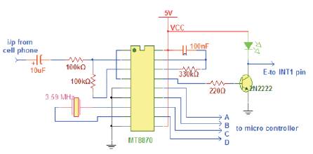
Figure 2. DTMF Decoder
As shown in Figure 3, a 40 pin, 8-bit micro controller 89C51 is used for controlling purpose. It receives 4-bit digital output from DTMF decoder on its port P1 pins P1.0 - P1.3. And interrupt signal is given to P3.3 (external interrupt 1) pin. It drives two DC motors through port P2 pins and two servo motors through port P0 pins P0.0 & P0.1. A crystal with two 33pf capacitors is connected to pins (18 & 19) to provide the basic clock signal to micro controller. One push button switch (RST) in parallel with 100nF capacitor forms power on reset circuit to reset the micro controller. It will control the movement of robot depending upon the code it receives from DTMF decoder which is shown in Table 1.
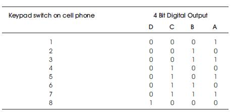
Table 1. Four bit digital output corresponding to keypad switch on cell phone
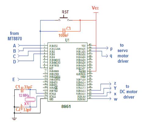
Figure 3. Microcontroller 8951
As shown in Figure 4, L293D is quadruple H-Bridge driver chip that is widely used for DC motor and stepper motor driver applications. It receives inputs from micro controller as shown on its input pins 2,7,10 & 15 and rotates two DC motors in either direction which is shown in Table 2.
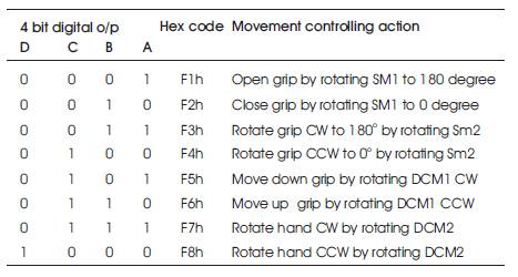
Table 2. Movement controlling action based on four bit digital output
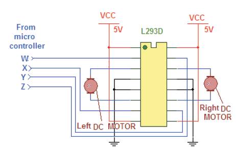
Figure 4. DC Motor Driver
Thus, to rotate left motor CW micro controller has to send byte 01h on port P2. Likewise 02h will rotate left motor CCW and so on (Table 3).
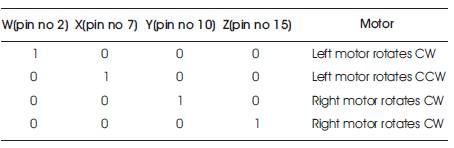
Table 3. Motor rotation based on microcontroller output pins
It receives the actuating signals from micro controller in terms of negative pulses, inverts it and provides required current to rotate 2 servo motors in both directions.
In Figure 5, two IC555 (configured in mono stable mode) are used to drive Servo Motors. It receives the negative pulse as an input from micro controller on its trigger input pin and produces exactly same inverted (positive pulse) output of same pulse width and drives the Servo Motor. The Servo Motor rotates on applied input pulse width. It rotates 180° when given pulse width is 5 ms and moves back to 0° position, when given pulse width is of 1ms. To retain the position, successive pulses of same width must be given after every 20 ms to the motor. So micro controller gives 3 consecutive negative pulse of 5 ms after 20 ms time period. This will move the motor to complete 180° in 3 to 4 steps.
Figure 5. Servo Motor
Robotic arm is in ideal condition without any joint movement (Figure 6).
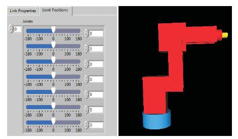
Figure 6. Robotic Arm Movement 1 via LabVIEW
Robotic Arm, base joint moved from 0° to -52.8° and it is able to move from -180° to180° (Figure 7).
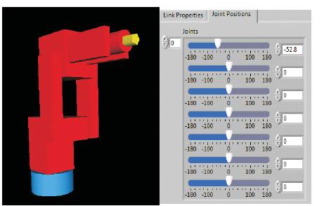
Figure 7. Robotic Arm Movement 2 via LabVIEW
Robotic arm, shoulder joint movement moved from 0 degree to -76.8° and it is able to move from -180° to 180° (Figure 8).
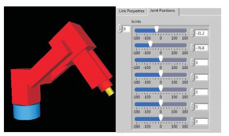
Figure 8. Robotic Arm Movement 3 via LabVIEW
Robotic arm, elbow joint movement moved from 0° to 57.6° and it is able to move from -180° to 180° (Figure 9).
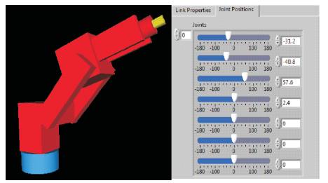
Figure 9. Robotic Arm Movement 4 via LabVIEW
Robotic arm, mid joint between Shoulder joint and wrist joint movement moved from 0° to -50.4° and it is able to move from -180° to 180° (Figure 10).
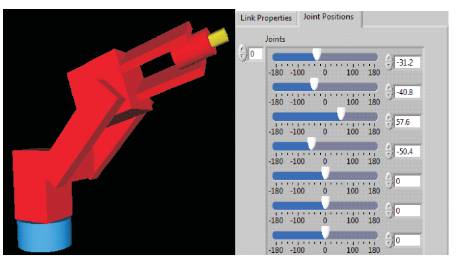
Figure 10. Robotic Arm Movement 5 via LabVIEW
Robotic arm, wrist joint movement moved from 0° to -57.6° and it is able to move from -180° to 180° (Figure 11).
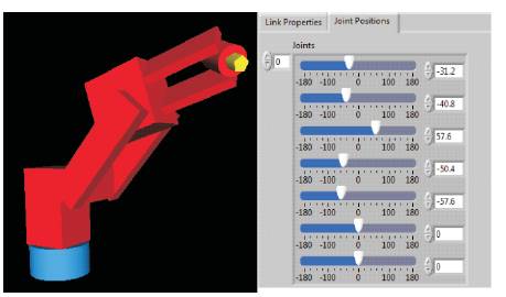
Figure 11. Robotic Arm Movement 6 via LabVIEW
Robotic arm, end-effectors movement moved in clockwise and anti clockwise from 0° to -33.6° and 0° to 4.8° and it is able to move from -180° to 180° (Figure 12). Figure 13 shows the Motor control via Proteus.
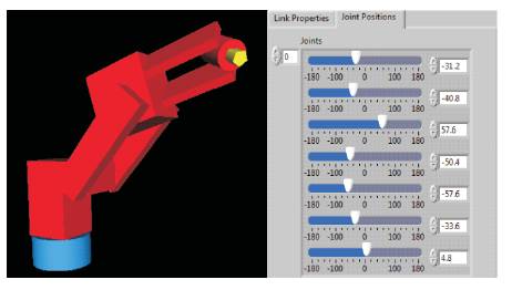
Figure 12. Robotic Arm Movement 7 via LabVIEW

Figure 13. Motor control via Proteus
A coconut-climbing device that will ultimately harvest coconuts would be a significant innovation for many people. Overlapping the fields of education and community service create a fantastic opportunity for young inventors. This learning experience will allow us to serve not just the local community, but the world at large. It is an opportunity of a lifetime.