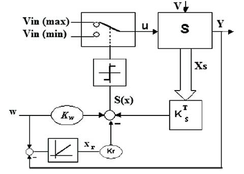
Figure 1. Configuration With Switching Law By Regulator
This project shows the use of optimization techniques for DC-DC buck and boost converter. Nowadays, dc-dc converters are used in many applications. The sliding mode control based on variable structure system theory has been examined by buck and boost switching mode converter type. In this project, the dynamics response of both buck and boost converter can be increased by using some optimization techniques. The sliding mode control strategy has been proposed to ensure system stability even when the large input voltage and load variation, and the dynamic response can be increased. The sliding surface has been selected by assigning the poles combined with genetic algorithm which it will give sliding regime. The simulation result of the proposed genetic algorithm based SMC strategy is compared with the existing SMC. The proposed GA based SMC gives considerable improvement in faster output voltage response during load variation.
The Sliding Mode Control approach gives another way to employ the control action which manipulates the inherent variable structure environment of DC-DC buck and boost converters. Several tasks arise for the dc-dc buck and boost converter control design. First, the power devices of the dcdc converters have very complicated time-varying switching behavior [8]. Therefore, the dynamic model development of power converters is a challenge. Second, dc-dc converters as power conditioning devices typically have a wide range of operating conditions, further complicating the control design. Furthermore, the control input is bounded due to the physical limitations of power converters. Finally, safe operation requirement such as peak current limits may impose additional nonlinear constraints. In addition to a voltage feedback loop, Adaptive terminal sliding mode control is employed so as to improve the performance of dc-dc converter. Performance enhancements, including overshoot of inductor current, startup response and dynamic response can be achieved. In control theory, sliding mode control (SMC) is a form of Variable Structure Control (VSC). It is a nonlinear control method that can vary the dynamics of a nonlinear system by application of a high-frequency switching control. The multiple control structures are designed so that trajectories always move toward a switching condition, and hence the ultimate trajectory will not exist entirely within one control structure. Instead, the ultimate trajectory will slide along the boundaries of the control structures [1, 2]. The movement of the system as it slides along these boundaries is called a sliding mode. Intuitively, for a dynamic system, sliding mode control uses mostly infinite gain to force the trajectories to slide along the restricted sliding mode subspace [3]. The main strength of sliding mode control is its robustness, because the controller can be switching between two states. It need not be fixed and will not be sensitive to load variations that enter into the control channel. The control law is a discrete function; the sliding mode can be reached in finite time. Sliding Mode Control is a propriate robust control method for the systems, where modeling in accuracies, parameter variations and disturbances are present. It is computationally simple compared to adaptive controllers with parameter estimation [4]. The Adaptive Terminal Sliding Mode Control (ATSMC) introduced in [5] has the advantages of assuring finite time convergence of the output voltage error to the equilibrium point and integrates an adaptive law to the TSMC strategy so as to make the sliding line dynamic during the load variations. In SMC, whenever the load changes, the output voltage should be constant. It also reduces the chattering in output voltage [2] A simple and systematic approach to the design of practical SMC has been presented in [6]. The adaptive feedforward and feedback based SMC strategy introduced in [5] has the advantages of adjusting the hysteresis width according to the input voltage change and the sliding coefficient according to the load change. The indirect SMC via double integral sliding surface strategy introduced in [7] reduces the steady-state error in the output voltage at the expense of having additional two states of sliding surface. The SMC has two steps: first, design the control law and second one is sliding surface.
The sliding surface has been selected by assigning pole combined with genetic algorithm [1]. It can increase the dynamic response. In [3], a time-optimal based SMC has been presented to improve the output voltage regulation of the converter subjected to any disturbance. The performance of PID sliding mode voltage control (PIDSMVC) strategy in [10,12] can be guided to improved robustness in providing consistent, transient responses over a wide range of operating conditions. In this paper, a Sliding Mode Control strategy based on the variable structure theory is proposed for the DC–DC buck converter. The main contribution in this paper is the use of assigned pole method combined with genetic algorithms for determination of the best control parameters. The assigned pole is used as a successful method to delimit the robust control parameters zone. The combination of genetic algorithm with the assigned pole method will allow further delimiting the best robust poles in this zone [9]. In view of this, a fixed frequency, which is based on an indirect Sliding Mode Control technique is implemented in Pulse Width Modulation (PWM). This controller can offer good large signal control performances with fast dynamical response [11].
To complete the design, the authors describe another function which can be added to limit the overshoot of inductor current. In this paper, they show the simple approach to increase the dynamic response of both buck and boost converters. Nowadays dc –dc converters are used in many applications such as motor drive power supply in personal computer and communication equipment. In buck type converter, output voltage is smaller than the input voltage, whereas in boost type converter, the output voltage is larger than the input voltage.
The Sliding Mode Control is established on the variable structure theory, and introduces to the complete system a good dynamic response and also robustness to large load and input voltage variations. The Sliding Mode Control operates in a simple way as follows; a sliding surface is defined with the equilibrium point , and the system is forced to be held into the sliding surface (existence condition), and then the system must reach the equilibrium point (stability). In order to encourage that the controlled system operates properly, the existence condition and stability must be verified. These are given by controller design steps; first step is to design control law and second one is sliding surface and also the system modeling could be considered as a design step [13– 15]. Using this model which reproduces the covering of the rectified current and the output voltage, the Variable Structure Systems Theory and the associated sliding mode behaviors can be applied to the DC–DC converter to control energy transfer from input voltage to output voltage. The sliding mode behavior is obtained by combining either a powering mode and free mode or a powering mode and regeneration mode [16]. Where S(x, t) is the switching surface consisting of the state feedback (Figure 1).
Figure 1. Configuration With Switching Law By Regulator
To demonstrate the underlying principal, the state space explanation of the buck and boost converter under Sliding Mode Voltage Control, where the control parameters are the output voltage, output voltage error dynamic, inductor current and reference voltage (in phase canonical form), is first discussed [17]. This section tells the theoretical explanation of the SMC converter .A practical method of designing the sliding coefficients is also introduced.
Using the current in the capacitor Ic (t) and the output c voltage Vo (t) as state variables, the state space equation o involving the simple model with integral action to avoid static error voltage in steady state is:
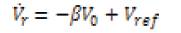
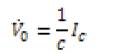
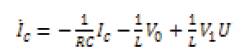
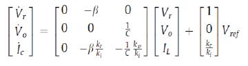
where C, L, and RL are the capacitance, inductance, and load resistance respectively; Vref , Vi, b. Vo and IL are the reference, input, sensed, output voltage and inductance current respectively, and U = 1 or 0 is the switching state of power switch SW. Then, the state space model of the system can be derived as:

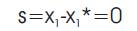
The simple idea of SM control is to design a certain sliding surface in its control law that will direct the trajectory of the state variables towards a desired origin when coincided [2]. The sliding mode controller has a switching function,
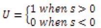
Where
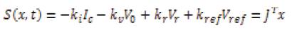
Where JT = [ ki kv kf kref ] and ki, kv , kf and kref are time –invariant sliding coefficients.,
As in all other SMC schemes, the determination of the ranges of employable sliding coefficients for the SMC converter must go through the process of analyzing the existence condition of the controller/converter system using the pole assigned method. In this controller design, they can improve the performance of both buck and boost converter.
Figure 2 shows the Sliding Mode Controlled dc-dc buck converter. The schematic diagram of the proposed dc-dc converter is derived from the state space model. This model consist of two main parts, one is controller part and another one is plant. Here they use Sliding Mode Controller which, can be increased.

Figure 2. DC-DC Buck Converter Using SMC
The variables used in dc-dc buck converter are
L : loop inductor; C : storage capacitor; R : load resistance;
E : source voltage;
I : input current; V : output voltage; u : switching signal taking value from the discrete set
U =:{0, 1}.
The dynamic model of the Buck type converter is given by,
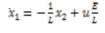
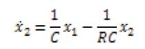
x1 = I and x2 =V, control u can take two values 0 or 1.
The goal of control is to make output voltage to be equal to the desired value Vd (t). The problem can be reformulated in terms of current control: the state function u should be found such that current x1 is equal to x1 *.
The control is selected in the form,

to enforce sliding mode in the region
The sliding mode exists if the values
are opposite signs. If Vd is constant, the sliding mode if 0 < Vd < E
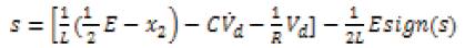
The state space equations describing sliding motion are obtained when the discontinuous control U is replaced by the equivalent control Ueq (x,t) Thus:
The above equation can be written as follows:

The dynamics behavior in sliding mode is determined by the characteristics equation:
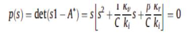
Let us notice that a root of the characteristic equation is null because of the linear dependence of the variables of state when the system is in sliding mode S(x, t) = 0. The dynamics of the system is thus influenced by the parameters of the sliding surface kv / ki , kr / ki and the time constant of the filter RLC.
However, the dynamics of the system is not affected by the variations of the voltage Vi, the inductance L and the load. This is due to an inherent quality of the sliding modes which is the robustness.
GA is a stochastic global adaptive search optimization technique based on the mechanisms of natural selection. Nowadays, GA has been accepted as an effective and efficient technique to solve optimization problems. GA is superior in avoiding local minima which is a common aspect of nonlinear systems. Furthermore, GA is a derivative-free optimization technique which makes it more attractive for applications that involve non-smooth or noisy signals.
GA starts with an initial population containing a number of chromosomes where each one represents a solution of the problem for which performance is evaluated by a fitness function. Basically, GA consists of three main stages; selection, crossover and mutation.
Selection is the process of choosing two parents from the population for crossing. After deciding on an encoding, the next step is to decide how to perform selection, i.e., how to choose individuals in the population that will create offspring for the next generation and how many offspring each will create. The purpose of selection is to emphasize fitter individuals in the population in hopes that their off springs have higher fitness. Chromosomes are selected from the initial population to be parents for reproduction. The problem is how to select these chromosomes. According to Darwin's theory of evolution, the best ones survive to create new offspring. Selection is a method that randomly picks chromosomes out of the population according to their evaluation function.
The higher the fitness function, the more chance an individual has to be selected. The selection pressure is defined as the degree to which the better individuals are favored. The higher the selection pressure, the more the better individuals are favored. This selection pressure drives the GA to improve the population fitness over successive generations.
After the selection stage, the genetic crossover operation is then applied between parent pairs from the mating pool to generate the new individuals or offspring which acquire good features from their parents. This crossover operation is performed with a crossover probability (Pc). The crossover operation can be a one-pointer or a double-point operation.
After crossover, the strings are subjected to mutation. Mutation prevents the algorithm to be trapped in a local minimum. Mutation plays the role of recovering the lost genetic materials as well as for randomly disturbing genetic information. It is an insurance policy against the irreversible loss of genetic material. Mutation has traditionally been considered as a simple search operator. If crossover is supposed to exploit the current solution to find better ones, mutation is supposed to help for the exploration of the whole search space. Mutation is viewed as a background operator to maintain genetic diversity in the population. It introduces new genetic structures in the population by randomly modifying some of its building blocks. Mutation helps escape from local minima's trap and maintains diversity in the population. It also keeps the gene pool well stocked, thus ensuring ergodicity. A search space is said to be ergodic if there is a non-zero probability of generating any solution from any population state. The mutation operation is performed with a mutation probability (Pm) which is usually low to preserve good chromosomes and to mimic real life where mutation rarely happens. The application of these three basic operations allows the creation of new individuals which may be better than their parents. This algorithm is repeated for many generations and finally stops when reaching individuals which provide an optimum solution to the problem. The application of these three basic operations allow the creation of new individuals which may be better than their parents. This algorithm is repeated for many generations and finally stops when reaching individuals that represent the optimum solution to the problem.
Figure 3 shows the simulation circuit diagram of dc-dc boost converter using sliding mode controller. The parameters which are used in simulation are mentioned in Table 1 the output of dc-dc buck and boost converter is given in Figure 4 and Figure 5 respectively. In buck converter, the output voltage is smaller than input voltage, whereas in boost converter, the output voltage is larger than the input voltage. The output of dc-dc boost converter is shown in Figure 5.

Table 1. Speification of DC-DC Buck and Boost Converter
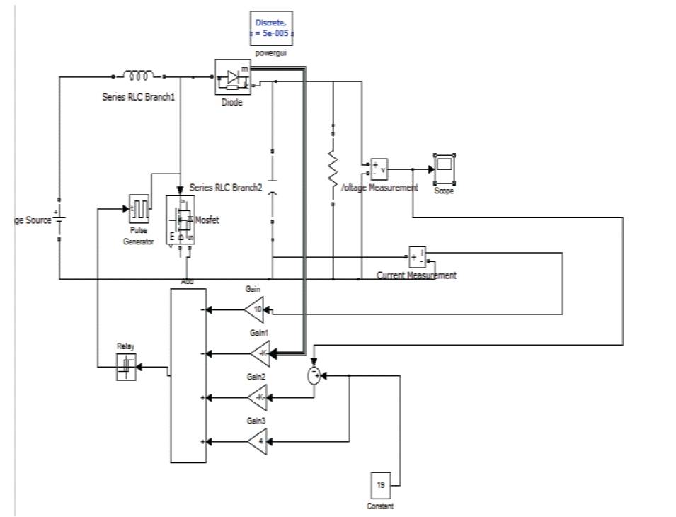
Figure 3. DC-DC Boost Converter Using SMC
Figure 4. Output of Dc-Dc Buck Converter
The simulation result shows that the SMC algorithms successfully achieved the dynamic response of DC-DC Buck and Boost. The implementation of Sliding Mode Control is used to improve the performance of buck and boost converter.
The simulation diagrams of boost converter clearly show that the output voltage has been maintained constant, even though the load has changed.