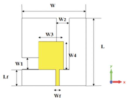
Figure1. Geometry of the proposed antenna
A novel open end slot antenna for UWB application is proposed in this paper. It occupies a compact size of 23.5×23.5mm2 . Multiple resonances are generated by using an asymmetrical rectangular patch with the L-shaped open-slot structure. The proposed antenna provides wide bandwidth from 3.1 GHz to 11.02.6 GHz with -10 dB return loss.
Due to the rapid development of Wireless communication systems, antennas are required to be simple in structure, compact in size and stable radiation pattern while retaining an extremely broad operating frequency range. The UWB antennas are developed to achieve a good impedance matching and the radiation pattern over a wider 3.1GHz to 10.6GHz frequency range. Compared with the traditional wide band antennas such as Vivaldi, log-periodic and spirals, slot antenna becomes an attractive candidate to realize a broadband and ultra-wideband characteristics due to its low profile, wide bandwidth, compact size, low cost, and ease of fabrication. When a slot antenna is fed by a micro strip line, it does not add weight and size to the system and is suitable for portable applications. A variety of printed slot antenna configurations have been reported in the open literature[3]–[7], including straight slot, wide slot, Lshaped slot, inverted T-slot, U slot, step slot, and fractalshaped slot, these wide slot antennas can achieve a good ultra-wideband characteristic. On the other hand, some slot antennas have limited to bandwidth, which was not enough for more applications. A tapered slot is used in the design of an antenna for lower Ultra Wide-Band (UWB) (3.1– 4.85 GHz) applications [8], but the bandwidth is too limited to meet the demands for UWB systems. An inverted-Lshaped open slot antenna[9], U-shaped slot[1] and a linear tapered slot antenna [10] are presented to enhance the impedance bandwidth. In [11], a stepped-slot antenna is effective in enhancing the bandwidth (3–11 GHz). However, its size is slightly larger. Therefore, it is important to further reduce the size of the antenna.
In this work, a novel open-end L shaped slot antenna is presented. The proposed antenna provides wide bandwidth from 3.1 GHz to 11.02GHz with -10dB return loss. The effects of the key structure parameters on the antenna performances are also analyzed and discussed.
The geometry of the proposed open-slot antenna is shown in Figure 1. The antenna is printed on an FR4 substrate with thickness h=0.8, relative permittivity, εr=4.6. The dimensions of the substrate are 23.5×23.5mm2 (L×W).This proposed open-slot antenna has a rectangular patch on the top side of the substrate, which is fed by a 50 microstrip line of width (Wf)and length (Lf). The patch size is optimized to achieve a miniaturized design. A L-shaped open slot is etched on the ground plane to enhance the bandwidth in the opposite side. By using the asymmetrical rectangular patch and the L-shaped open slot[2], a wideband impedance characteristic (3.1-11.02GHz) can be obtained. The design evolution of the open-slot antenna is shown in Figure 2, and the corresponding simulated return losses are shown in Figures 3 and 4. For detailed design, all parameters of the antennas are simulated using the CST microwave studio and are given in Table 1.
Figure1. Geometry of the proposed antenna
It begins with the design of Antenna 1, which consists of a straight micro strip feed line and an L-shaped open slot. As shown in Figure 2, when the slot antenna is fed by a straight line, a -10-dB return loss in bandwidth from 4 to 5 GHz is achieved. After using a rectangular patch instead of the straight micro strip line (Antenna 2), the antenna can get three relative impedance bandwidths with -10-dB return loss of (3–4GHz), (5–6 GHz), and (6–7 GHz), respectively. However, it still cannot satisfy the requirement for UWB systems. The impedance characteristics of the slot antenna may mainly suffer from strong ground-plane effect.
It is worth mentioning that when the rectangular patch of the antenna is asymmetrically fed by a 50- Ω micro strip line, multiple resonances can be generated in the operating band. However, the impedance matching of the antenna is poor, especially at the lower frequencies. To improve the impedance matching of the proposed design as shown in Figure 1, the proposed antenna could get an ultra-wide impedance bandwidth with good impedance matching and its simulated -10-dB return loss bandwidth is up to 3.5 –10.6GHz, as shown in Figure 5.
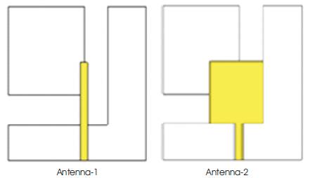
Figure 2. Design evolution of the proposed Antenna
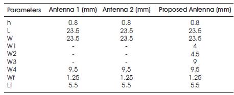
Table 1. Parameters of the Antennas
Figure 5 shows the simulated return loss of the proposed antenna. From Figure 5, it can be observed that the combination of the L-shaped open slot and the asymmetrical rectangular patch could produce the multiple resonant frequencies covering the UWB band. The rectangular patch affects resonances at 5–9 GHz, and the resonance mode at lower frequency is due to the open slot.
The L-shaped slot comprises of one vertical slot and one horizontal slot. The width of the vertical slot (W4) affects impedance bandwidth of the proposed antenna. The width of the horizontal slot (W2) affects the impedance matching of the proposed slot antenna. When increasing W4 =4.5mm and W2= 4 mm impedance matching and impedance bandwidth is significantly improved.
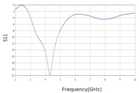
Figure 3. Simulated Return Loss of Antenna-1
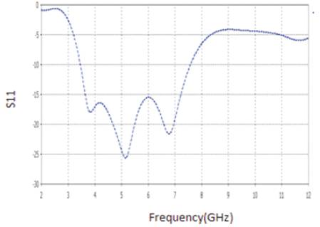
Figure 4. Simulated Return Loss of Antenna-2
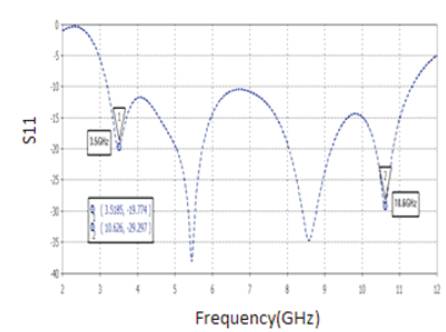
Figure 5. Simulated Return Loss of Proposed Antenna
The gap distance between the separate ground plane and the lower edge of the L-shaped ground plane plays an important role in impedance matching, especially at higher frequencies. The simulated radiation patterns at 3.5GHz, 5.4GHz, 8.5GHz and 10.6 GHz are plotted in Figure 6.
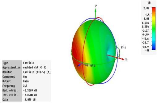
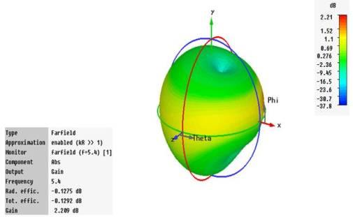

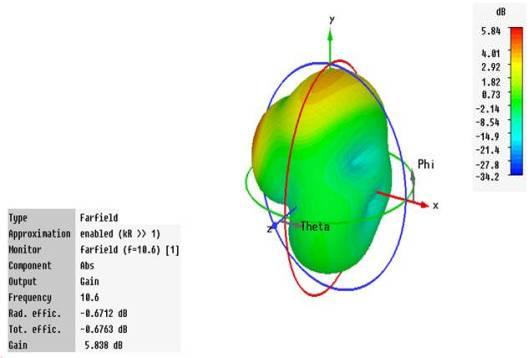
Figure 6. 3D View of Radiation Pattern and gain at 3.5, 5.4, 8.5 and 10.6 Ghz
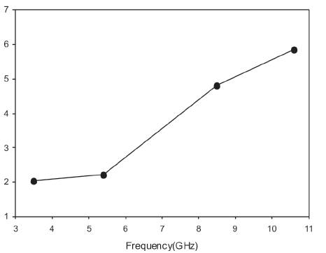
Figure 7. Simulated gain for various frequencies
The average gain in the 3.5–10.6 GHz operating band is observed to be 3.7 dB. The maximum value is about 5.8dB at 10.6GHz as shown in Figure 7. As a result, the gains of the proposed antenna within the operating band are enough to meet the requirement for UWB systems. It is interesting to find that the proposed antenna size was reduced when compared with the previous antenna design. It is operating in ultra-wide band frequency range.
A novel compact open-ended slot antenna for UWB application and bandwidth enhancement is presented. By using an asymmetrical rectangular patch with the Lshaped open-slot structure, the impedance bandwidth of the designed antenna is improved. Effects of key parameters on the antenna performances are also investigated. The proposed antenna features an ultra-wide impedance bandwidth from 3.1to 11.02 GHz with a small size, which is very suitable for portable UWB applications.