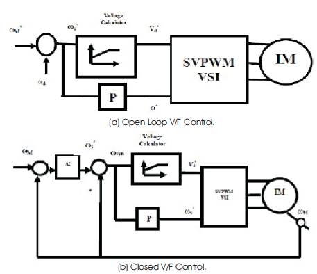
Figure 1. Basic V/F control of induction motor
Induction Motors have many applications in the industries, because of the low maintenance and robustness. The speed control of induction motor is more important to achieve maximum torque and efficiency. The rapid development of power electronic devices and converter technologies in the past few decades, has made possible efficient speed control by varying the supply frequency and voltage, giving rise to various forms of adjustable-speed Induction Motor drives. In about the same period, there were also advances in control methods and Artificial Intelligence (AI) techniques, including expert system, fuzzy logic, neural networks and genetic algorithm. Researchers soon realized that the performance of induction motor drives can be enhanced by adopting Artificial Intelligent based methods. This paper presents an integrated environment for speed control of Induction Motor (IM) using artificial intelligent controller. The integrated environment allows users to compare simulation results between classical and artificial intelligent controllers. The fuzzy logic controller and artificial neural network controllers are also introduced to the system for keeping the motor speed to be constant when the load varies. The performance of fuzzy logic and artificial neural network based controllers is compared with that of the conventional proportional integral controller. The performance of the Induction motor drive has been analyzed for constant and variable loads.
Induction motors (IMs) have been used as the workhorse in industry for a long time due to their easy build, high robustness, and generally satisfactory efficiency[1]. In recent years, the scientists and researchers have acquired significant development on various sorts of control theories and methods. Among these control technologies, intelligent control methods, which are generally regarded as the aggregation of fuzzy logic control, neural network control, genetic algorithm, and expert system, have exhibited particular superiorities. Artificial Intelligent Controller (AIC) could be the best controller for Induction Motor control. Over the last two decades, the researchers have been working to apply AIC for induction motor drives [1-6]. This is because, AIC possesses advantages as compared to the conventional PI, PID (Proportional- Integral-Derivative) controller and their adaptive versions. Mostly, it is often difficult to develop an accurate system mathematical model since, the unknown and unavoidable parameter variations, and unknown load variations occur due to disturbances, saturation and variation temperature. High accuracy is not usually imperative for most of the induction motor drives, however for high performance IM drive applications, a desirable control performance in both transient and steady states must be provided even when the parameters and load of the motor are varying during the operation. Controllers with fixed parameters cannot provide these requirement, unless unrealistically high gains are used. Thus, the conventional constant gain controller used in the variable speed induction motor drives become poor when the uncertainties of the drive such as load disturbance, mechanical parameter variations and unmodelled dynamics occur in practical applications. Therefore, control strategy must be adaptive and robust. As a result, several control strategies have been developed for induction motor drives with at least two decades. This paper presents the speed control scheme of scalar controlled induction motor drive in open loop and closed loop mode, that involves decoupling of the speed and ref speed into torque and flux producing components. Fuzzy logic, artificial neural network and Adaptive Neuro-Fuzzy controller (ANFIS) based control scheme has been simulated. The performance of fuzzy logic, artificial neural network and Adaptive Neuro- Fuzzy controller (ANFIS ) based controllers is compared with that of the conventional proportional integral controller in open loop and closed loop. The dynamic modeling of Induction motor is done and the performance of the Induction motor drive has been analyzed for constant and variable loads. Figure1 shows the proposed control scheme for an induction motor in open loop and closed loop [9-12].
Figure 1. Basic V/F control of induction motor
The induction motors dynamic behavior can be expressed by voltage and torque which are time varying. The differential equations that belong to dynamic analysis of induction motor are so sophisticated. Then, with the change of variables, the complexity of these equations decrease through the movement from poly phase winding to two phase winding (q-d). In other words, the stator and rotor variables like voltage, current and flux linkages of an induction machine are transferred to another reference model which remains stationary[1-6].
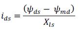
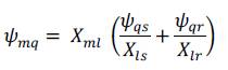
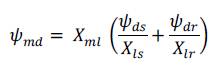
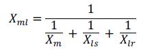
In Figure 2, stator inductance is the sum of the stator leakage inductance and magnetizing inductance (Lls = Ls + Lm), and the rotor inductance is the sum of the rotor leakage inductance and magnetizing inductance (Llr = Lr + Lm). From the equivalent circuit of the induction motor in d-q frame, the model equations are derived. The flux linkages can be achieved as
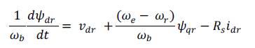
By substituting the values of flux linkages in the above equations, the following current equations are obtained as:

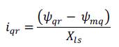
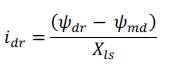
Where ψmq and ψmd are the flux linkages over Lm in the q and d axes. The flux equations are written as follows
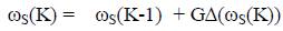
In the above equations, the speed ωr is related to the torque by the following mechanical dynamic equation as:
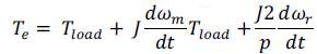
ωr is achievable from above equation, where:
p: number of poles.
J: moment of inertia (kg/m2 ).
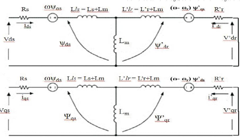
Figure 2. d q Model of Induction Motor
In the previous section, dynamic model of an induction motor was expressed. The model constructed according to the equations has been simulated by using MATLAB/ SIMULINK as shown in Figure 3 in open loop and closed loop mode with PI controller of operation of induction motor. A 3 phase source is applied to the conventional model of an induction motor and the equations are given by:
By using Parks Transformation, voltages are transformed into two phase in the d-q axes, and are applied to induction motor. In order to obtain the stator and rotor currents of induction motor in two phases, Inverse parks transformation is applied in the last stage[6].
Scalar control method is widely used in industries due to its simple structure characterized by low steady-state error.
Proportional Integral (PI) controllers are commonly used in scalar speed control of induction motors in addition to AI controllers. A mathematical model of the real plant is required for the controller design with conventional methods. The difficulty of identifying the accurate parameters for a complex nonlinear and time-varying nature of real plants may render, in many cases, the fine tuning of parameters which is time consuming. PI controllers are very much sensitive to parameter variations inherent in real plant operations. The PI control is given by
The output of the PI controller is updated by updating the PI controller gains (Kp and Ki) based on the control law in the presence of parameter variation and drive nonlinearity. The use of PI controllers for speed control of induction machine drives are characterized by an overshoot during tracking mode and a poor load disturbance rejection. This is mainly caused by the fact that the complexity of the system does not allow the gains of the PI controller to exceed a certain low value.
If the gains of the controller exceed a certain value, the variations in the command torque controller gains are very high. The motor reaches the reference speed rapidly and without overshoot, step commands are tracked with almost zero steady state error and no overshoot, load disturbances are rapidly rejected and variations of some of the motor parameters are fairly well dealt by becoming too high which will destabilize the system. To overcome this problem the authors propose the use of a limiter ahead of the PI controller [11]. This limiter causes the speed error to be maintained within the saturation limits. Figure 4 shows the structure of PI controller.
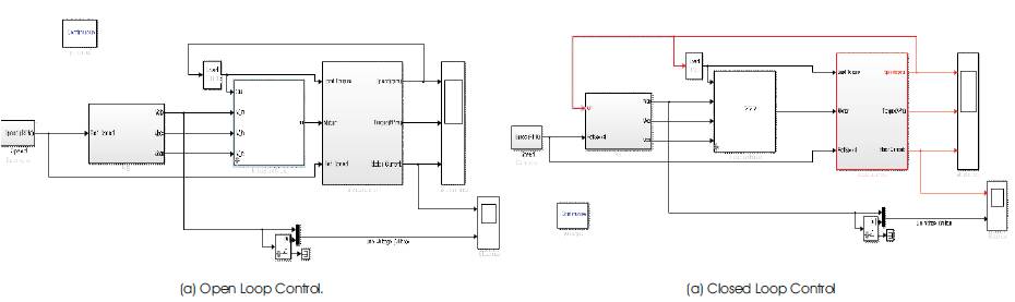
Figure 3. Simulated Induction Motor Model with PI Controller
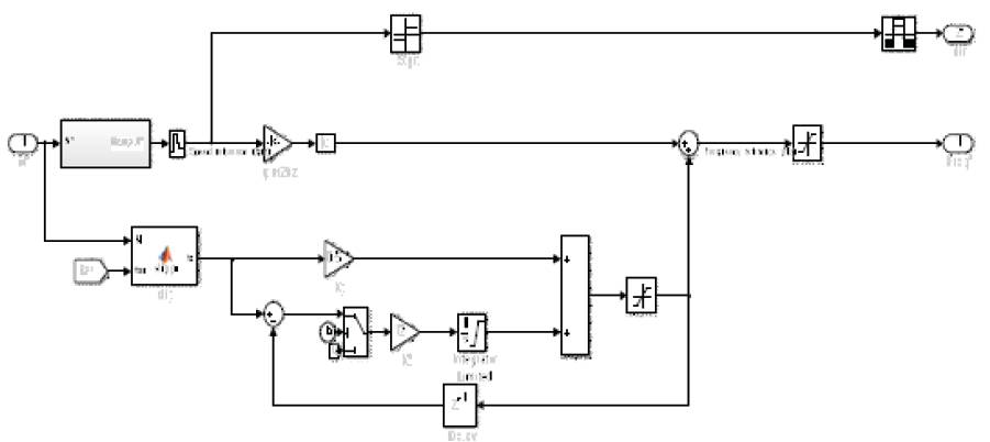
Figure 4. PI controller
Despite the great efforts devoted to induction motor control, many of the theoretical results cannot be directly applied to practical systems. Intelligent control techniques are generally classified as expert system control, fuzzy-logic control, neural network control and genetic algorithm. Various artificial intelligent controllers are as follows.
The speed of an induction motor is adjusted by the fuzzy controller. In Table 1, the fuzzy rules decision implemented in the controller are given. The conventional simulated induction motor model as shown in Figure 3 is modified by adding Fuzzy controller and is shown in Figure 5. Speed output terminal of induction motor is applied as an input to fuzzy controller, and in the initial start of induction motor the error is maximum, so according to fuzzy rules FC produces a crisp value. Then this value will change the frequency of sine wave in the speed controller. The sine wave is then compared with triangular waveform to generate the firing signals of IGBTs in the PWM inverters. The frequency of these firing signals also gradually changes, thus increasing the frequency of applied voltage to Induction Motor [12-14]. As discussed earlier, the crisp value obtained from Fuzzy Logic Controller is used to change the frequency of gating signals of PWM inverter. Thus the output AC signals obtained will be variable frequency sine waves. The sine wave is generated with amplitude, phase and frequency which are supplied through a GUI. Then the clock signal which is sampling time of simulation is divided by the crisp value which is obtained from FLC. So by placing three sine waves with different phases, one can compare them with triangular waveform and generate necessary gating signals of PWM inverter. So that at the first sampling point, the speed is zero and error is maximum. Then, whatever, the speed rises, the error will decrease, and the crisp value obtained from FLC will increase. So, the frequency of sine wave will decrease which will cause IGBTs switched ON and OFF faster. It will increase the AC supply frequency, and the motor will speed up. The inputs to these blocks are the gating signals which are produced in speed controller block. The firing signals are applied to IGBT gates that will turn ON and OFF the IGBTs.
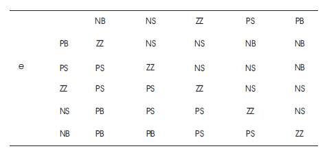
Table 1. Modified Fuzzy Rule Decision
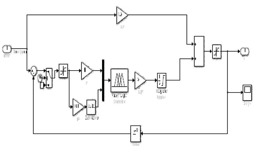
Figure 5. Modified Fuzzy Controller
One of the most important features of Artificial Neural Networks (ANN) is their ability to learn and improve their operation using a neural network training data[7-8]. The basic element of an ANN is the neuron which has a summer and an activation function. The mathematical model of a neuron is given by:
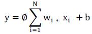
where (x1 , x2 … xN ) are the input signals of the neuron, (w1 ,w2 ,… wN ) are their corresponding weights and b is bias parameter. Φ is a tangent sigmoid function and y is the output signal of the neuron. The ANN can be trained by a learning algorithm which performs the adaptation of weights of the network iteratively until the error between target vectors and the output of the ANN is less than a predefined threshold. The most popular supervised learning algorithm is backpropagation, which consists of a forward and backward action. In the forward step, the free parameters of the network are fixed, and the input signals are propagated throughout the network from the first layer to the last layer. In the forward phase, they compute a mean square error.
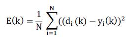
where di is the desired response, yi is the actual output produced by the network in response to the input xi, k is the iteration number and N is the number of input-output training data. The second step of the backward phase, the error signal E(k) is propagated throughout the network in the backward direction in order to perform adjustments upon the free parameters of the network in order to decrease the error E(k) in a statistical sense. The weights associated with the output layer of the network are therefore updated using the following formula
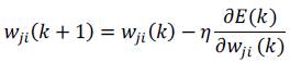
where wji is the weight connecting the jth neuron of the output layer to the ith neuron of the previous layer, η is the constant learning rate. The objective of this Neural Network Controller(NNC) is to develop a back propagation algorithm such that the output of the neural network speed observer can track the targeted one. Figure 6 depicts the network structure of the NNC, which indicates that the neural network has a three-layered network structure. The first is formed with five neuron inputs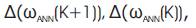

 The second layer consists of five neurons. The last one contains one neuron to give command variation
  The aim of the proposed NNC is to compute the command variation based on the future output variation
 Hence, with this structure, a predictive control with integrator has been realised. At time k, the neural network computes the command variation based on the output at time (k+1), while the latter isn’t defined at this time. In this case, it is assumed that
  The control law is deduced using the recurrent equation given by,
It can be seen that the d axis and q axis voltage equations are coupled by the terms dE and qE. These terms are considered as disturbances and are cancelled by using the proposed decoupling method. If the decoupling method is implemented, the flux component equations have become

Large values of η may accelerate the ANN learning and consequently fast convergence but may cause oscillations in the network output, whereas low values will cause slow convergence. Therefore, the value of η has to be chosen carefully to avoid instability. The proposed Neural Network controller is shown in Figure 6 [14-15].
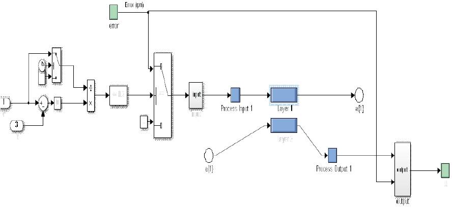
Figure 6. Neural Network Controller
AC motor drives are used in multitude of industrial and process applications requiring high performances. In high performance drive systems, the motor speed should closely follow a specified reference trajectory, regardless of any load disturbances and any model uncertainties. In the designing of a controller, the main criteria is the controllability of torque in an induction motor with good transient and steady state responses. With certain drawbacks, PI controller is able to achieve these characteristics. The main drawbacks are (i) The gains cannot be increased beyond certain limit. (ii) Non linearity is introduced, making the system more complex for analysis. With the advent of artificial intelligent techniques, these drawbacks can be mitigated. One such technique is the use of Fuzzy Logic in the design of controller either independently or in hybrid with PI controller. Adaptive Neuro- Fuzzy Inference System(ANFIS) replaces the draw-backs of Fuzzy Logic Control and Artificial Neural Network. Adaptive neuro fuzzy combines the learning power of neural network with knowledge representation of fuzzy logic. Neuro fuzzy techniques have emerged from the fusion of Artificial Neural Networks (ANN) and Fuzzy Inference Systems (FIS) and have become popular for solving the real world problems. A neuro fuzzy system is based on a fuzzy system which is trained by a learning algorithm derived from neural network theory. There are several methods to integrate ANN and FIS and very often the choice depends on the applications. In this paper, the inputs will be e(k) and Δe(k)[12-16]. Figure 7 shows the overall e(k) structure of Adaptive Neuro-Fuzzy model.
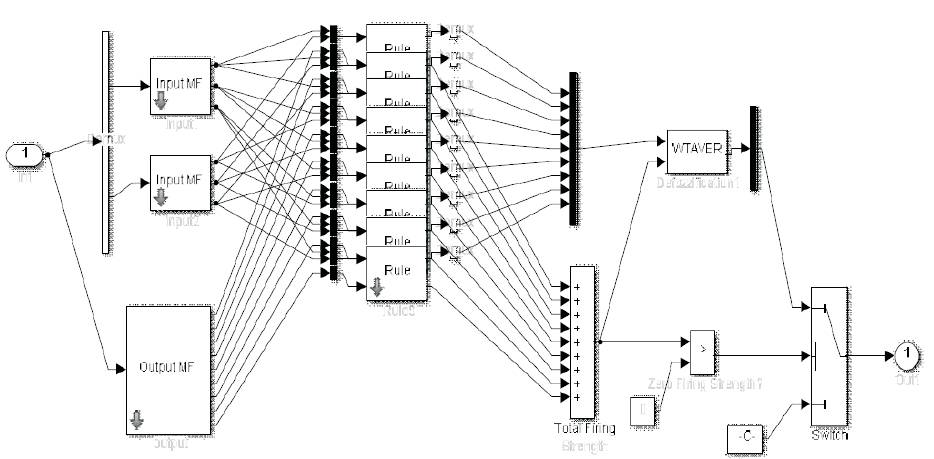
Figure 7. Adaptive Neuro-Fuzzy model
A complete simulation model for scalar v/f controlled Induction motor drive incorporating PI, Fuzzy Logic Controller, Neural network controller and ANFIS is developed in open loop and closed loop mode. V/F control of Induction motor drive with Fuzzy controller is designed by proper adjustments of membership functions ,Neural network controller is designed by adjusting the weights and ANFIS is developed on a fuzzy system which is trained by a learning algorithm derived from neural network theory in order to get simulated results. The performance of the artificial intelligent based induction motor drive is investigated at different operating conditions. In order to prove the superiority of the ANFIS, a comparison is made with the response of conventional PI, FLC and Neural Network based induction motor drive. The parameters of the induction motor considered in this study are summarized in Appendix ‘A’. The performances of the scalar controlled induction motor with all intelligent controllers are presented at constant load and variable load in open and closed loop mode. The dynamic behaviours of the PI controller, FLC controller, Neural Network controller and ANFIS are shown in Figures 8 to 19 at constant load and variable load conditions in open loop and closed loop mode.
A drive with PI controller has a peak overshoot, but in case of
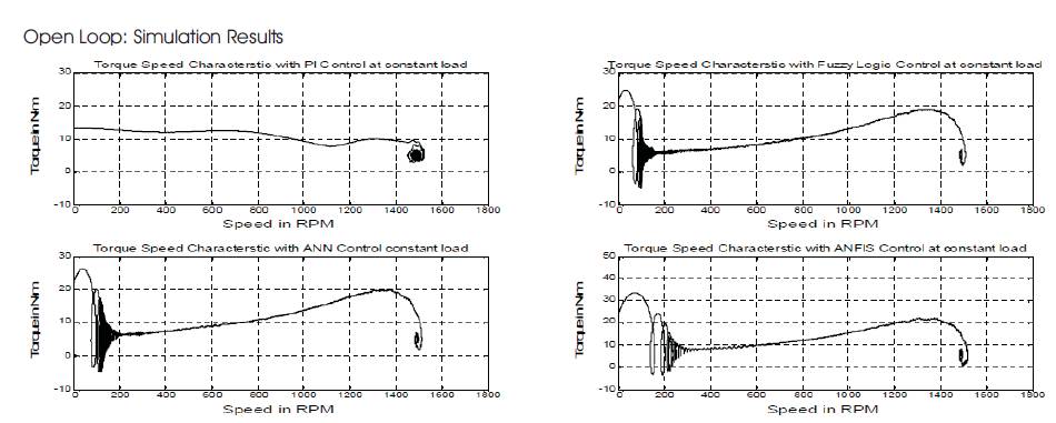
Figure 8. Torque –Speed Characteristics: AI controller at Const. Load
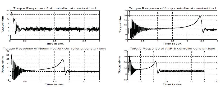
Figure 9. Torque Responses: AI Controller at Const Load
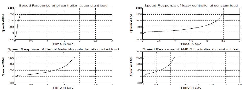
Figure 10. Speed Responses: AI Controller at Const. Load
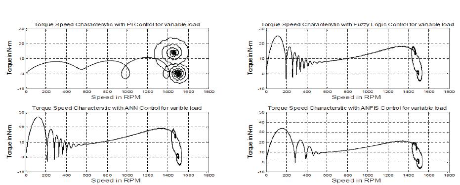
Figure 11. Torque –Speed Characteristics: AI controller at Variable Load
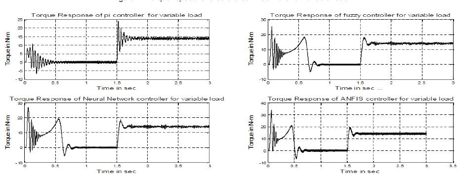
Figure 12. Torque Responses: AI Controller at Variable Load
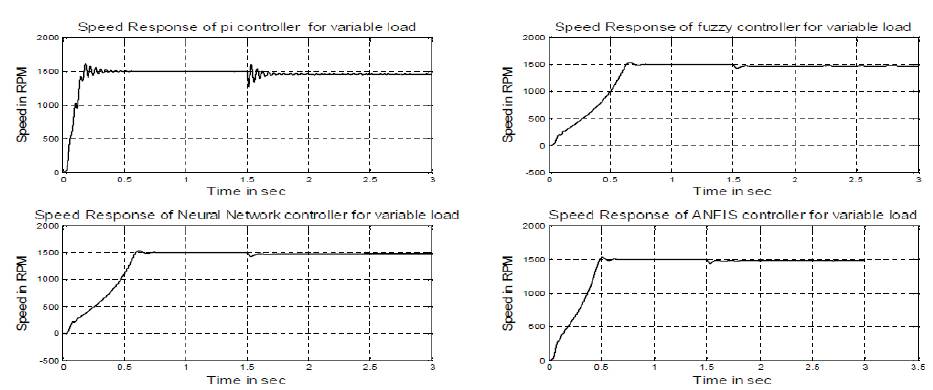
Figure 13. Speed Responses: AI Controller at Variable Load
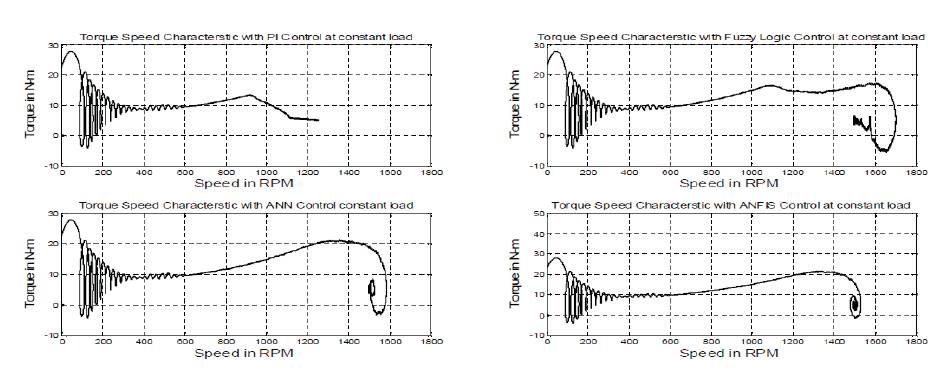
Figure 14. Torque –Speed Characteristics: AI controller at Const. Load
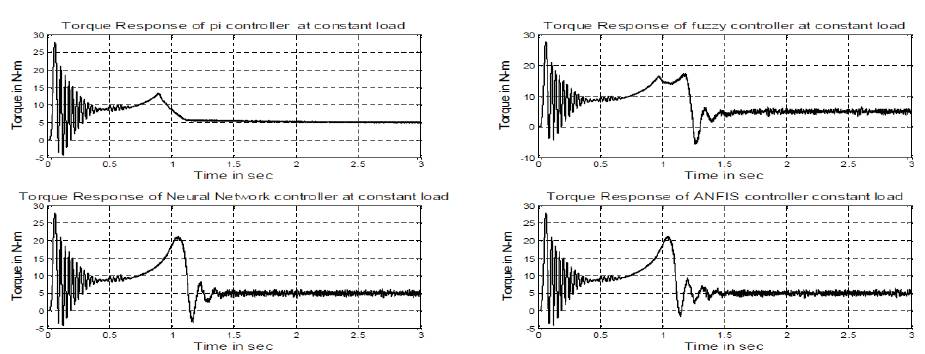
Figure 15. Torque Responses: AI Controller at Const Load
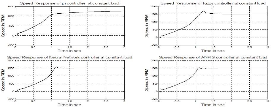
Figure 16. Speed Responses: AI Controller at Const. Load
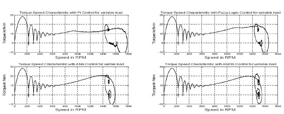
Figure 17. Torque –Speed Characteristics: AI controller at Variable Load
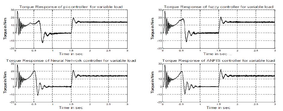
Figure 18. Torque Responses: AI Controller at Variable Load
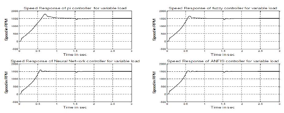
Figure 19. Speed Responses: AI Controller at Variable Load.
•At constant load conditions
A drive with PI controller has a peak overshoot, but in case of fuzzy controller, neural network controller and ANFIS, it is eliminated as shown in Figures 10 and 16. The PI controller is tuned at rated conditions in order to make a fair comparison. Figures 8, 9, 10 and 14, Figures 15, 16 show the simulated starting performance of the drive with conventional PI, FLC, neural and ANFIS based drive systems, in open loop and closed loop respectively. Although the PI controller is tuned by trial and error to give an optimum response at this rated condition, the ANFIS controller yields better performance in terms of faster response time and lower starting current. It is worth mentioning here that the performance obtained by the proposed AI controller is faster than the PI controller, i.e. it achieves the steady state condition faster than the PI controller.
• At variable load conditions
Drive with PI controller speed response has small peak at 0.6 sec, but in case of fuzzy controller, neural network and ANFIS controller speed response, it is quick and smooth response which is shown in Figures13 and 18. Figures11, 12, 13 and 17, Figures 18, 19 show the waveforms of Speed, Torque, Torque-Speed characteristics with four controllers. Figures 13 and 16 show the speed response for step change in the load torque using the PI, fuzzy, neural and ANFIS controller, respectively. The motor starts from standstill at load torque = 5 Nms and at t =0.6s, a sudden full load of 15 Nms is applied to the system, then it is controlled by fuzzy, neural and ANFIS controller. Since the time taken by the PI controlled system to achieve steady state is much higher than fuzzy, neural and ANFIS controlled system, the step change in load torque is applied at t = 3 sec. The motor speed follows its reference with zero steady-state error and a fast response using a fuzzy controller, neural and ANFIS. On the other hand, the PI controller shows steadystate error with a high starting current. It is to be noted that the speed response is affected by the load conditions. This is the drawback of a PI controller with varying operating conditions. It is to be noted that the neuro controller and ANFIS give better responses in terms of overshoot, steadystate error and fast response when compared with PI and fuzzy. These figures also show that the neuro and ANFIS controller based drive system can handle the sudden increase in command speed quickly without overshoot, under- shoot, and steady-state error, whereas the PI and fuzzy controller-based drive system has steady-state error and the response is not as fast as compared to neural network and ANFIS . Thus, the proposed ANFIS based drive has been found superior to the conventional PI-controller, FLC, ANFIS based system. [17]
Table 2 and 3 present the performance comparison during steady state operation and transient operation of three controllers.
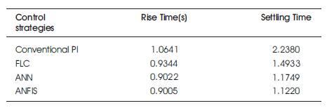
Table 2. Performance Comparison Between Pi, Fuzzy, Neural and ANFIS Controllers During Steady State Operation
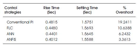
Table 3. Performance Comparison Between Pi, Fuzzy, Neural and ANFIS Controllers During Transient Operation
In this paper, simulation results of the induction motor are presented in conventional PI, FLC ,NN and ANFIS. As it is apparent from the speed curves in four models, the fuzzy controller drastically decreases the rise time, in the manner which the frequency of sine waves are changing according to the percentage of error from favorite speed. The frequency of these firing signals also gradually changes, thus increasing the frequency of applied voltage to Induction Motor. According to the direct relation of induction motor’s speed and frequency of supplied voltage, the speed also will increase. With the results obtained from simulation, it is clear that for the same operation condition of induction motor, fuzzy controller has better performance than the conventional PI controller. By comparing Adaptive neuro fuzzy model with FLC model, it is apparent that by adding learning algorithm to supplied voltage, the speed will also increase. With results obtained from simulation, it is clear that for the same operation condition of induction motor, fuzzy controller has better performance than the conventional PI controller. By comparing Neural network controller with FLC model, it is apparent that adding learning algorithm to the control system will decrease the rising time more than expectation and it proves that ANFIS controller has better dynamic performance as compared to NN, FLC and conventional PI controller. The comparative results prove that the performance of scalar v/f -control drive with ANFIS controller is superior to that with conventional PI, fuzzy and neural network controller. Thus, by using ANFIS controller, the transient response of induction machine has been improved greatly and the dynamic response of the same has been made faster. For variable loads, when there is a sudden change in load, the ANFIS controller reaches its steady state value faster and there are no overshoots as compared to the PI, Fuzzy and NN controller. This proves the robustness of ANFIS controller.
The following parameters of the induction motor are chosen for the simulation studies:
V = 380 f = 50Hz Rated Power = 1700Watts Rs = 4.1Ω Rr = 2.5Ω Ls = 0.545H Lr = 0.543H Lm = 0.510H PLM =0.5 H
p= 4 J = 0.02Kg-m2