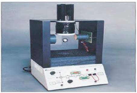
Figure 1. Schematic diagram of Maglev Setup 33-210
The Magnetic levitation system serves as a simple model of devices, which are becoming popular in recent years. Magnetic Levitation System is a nonlinear, unstable system that can be applied in many application area such as in magnetic bearings, high speed trains, vibration isolation tables in semiconductor manufacturing, levitation of wind power generation, levitation of molten metal in induction furnaces, position tracking and levitation of metal slabs during manufacturing. The Magnetic levitation system can be categorized as a repulsive system and this system is based on the source of levitate forces. Since it is highly nonlinear and unstable system, it is very challenging in order to construct the high performance controllers to regulate the position of the levitation ball. This work involves the design of PID controller, Optimized PID controller. The real time implementation on the magnetic levitation kit has been carried out.In the above work, we acquired a high precision control to levitate a steel ball in the desired position.
Magnetic levitation systems have acquired a great attention due to their practical importance. Maglev is a system of transportation that suspends guides and propels vehicles, dominantly trains. Maintenance problem caused by friction is completely eliminated, since it does not use long reaching and joining parts. Various other problems such as abrasion, lubrication, long endurance, controllable support force, adjustable stiffness, etc. can also be taken into account. Magnetic levitation systems are electromagnet devices that suspend ferromagnetic material using electromagnetism [2]. The controller is the heart of the magnetic levitation system, as it regulates the position of the steel ball at a desired height in an environment. It determines the carrying, stiffness and damping characteristics of the maglev support, and impacts the dynamic performance of the system [7]. Overshoot and settling time are the key factors which are to be considered while considering the maglev system. In this paper, we provide a real time PID controller and GA based PID controller implementation. In GA based PID control scheme, the optimal PID parameters are properly optimized using Genetic algorithm. Finally the performance criteria are analyzed for both the controllers.
Magnetic levitation system is ball suspension system which is used to levitate the 21 gram steel ball in air using electromagnetic force against the gravitational pull [9]. The magnetic levitation system shown in Figure 1 consists of an electromagnet, a steel ball, a position sensor, a data acquisition AD/DA board, a control computer and a drive circuit. The steel ball gets suspended in the desired position using electromagnetic force [6], which is generated by applying the current through the coil. The displacement of ball from the balance point is measured using the position sensor which is placed on either side of the casing. The sensor system gives the positions of the levitation object. The displacement signal [1] is then transmitted to the microprocessor, which works as the controller. The controller determines the control command from the desired position and the present position of the levitation object. The control signal is amplified and converted by the current drive, so that the levitation object can be moved to the desired position. In the magnetic ball levitation system, the magnetic characteristics appear to be functions of the structure of electromagnetic circuit, levitation object, and core material. A ferromagnetic material in a magnetic field can produce magnetic attractive force against the gravity. Every control project starts with plant modelling. Here we discuss about the mechanical model of the Magnetic levitation system.
Figure 1. Schematic diagram of Maglev Setup 33-210
The magnetic force applied by the electromagnet is opposite in direction compared to gravitational force and it maintains the suspended steel ball at a particular position [4]. The magnetic force F depends on the electromagnet current I, electromagnet characteristics and air gap x between the steel ball and the electromagnet. Figure 2 shows the working mechanism of the magnetic levitation system.
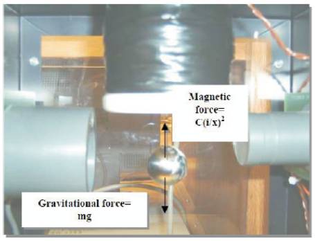
Figure 2. Force diagram
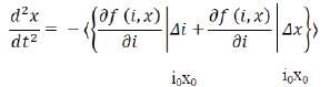
According to T. H. Wong, laboratory-scale maglev systems are represented with electrical and mechanical equations. To carry out analysis of the model dynamics for open loop systems using techniques such as Bode plots, poles and zeros maps, Nyquist plots, root locus (for closed loop systems only), the model has to be linearized [5]. Such a linearization is done in the equilibrium position of, x0= -1.5 V(the position is expressed in volts), i0= 0.8 A.The motion of the steel ball in the magnetic field [3] is given in equation (1).
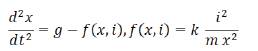
Where,
I- current of the coil (A)
x- position of the ball (m)
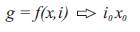
Equilibrium point can be calculated from:
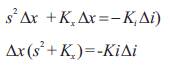
Linearization has been done in equation (2)
Where,
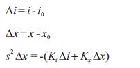
Ki - constant (N/A), Kx - constant (N/m)
Transfer function obtained for a desired operating point is given in equation (4)
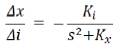
Where, Ki =2 mg /i0 and Kx =-2 mg/x0
The parameters considered for the magnetic levitation system is tabulated in Table I.
The open loop response of the magnetic levitation system MLS 33-210 is shown in Figure 3.
Figure 3 clearly explains that without any controller the system will be in unstable state. The electromagnet does not get magnetized due to the absence of control voltage. So the height keeps on increasing without attaining the steady state.
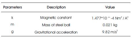
Table 1. Parameters of Maglev System
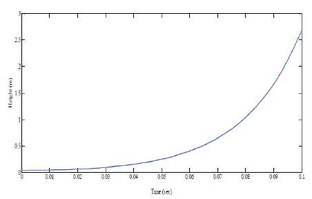
Figure 3. Open loop response
A PID controller is a generic control loop feedback mechanism widely used in industrial control systems. A PID controller calculates an error value as the difference between a measured process variable and a desired set point. The controller attempts to minimize the error by adjusting the process control inputs. The PID controller algorithm involves three separate constant parameters, and is accordingly called three-term control: the proportional, integral and derivative values. Heuristically, these values can be interpreted in terms of time. P depends on the present error, I on the accumulation of past errors, and D is a prediction of future errors, based on current rate of change. The weighted sum of these three actions is adjusted to the process via a control element such as position of a control valve or power supply of a heating element. In the absence of knowledge of the underlying process, a PID controller is the best controller by tuning three parameters in the PID controller algorithm, the controller can provide control action designed for specific process requirements. The response of the controller can be described in terms of the responsive of the controller to an error, the degree to which the controller overshoots the setpoint and the degree of system oscillation.
PID control scheme has been applied to the MLS33-210 system. The PID parameters are tuned using the Ziegler Nicholas closed loop method. As per the above method, at a particular value of proportional constant, the maglev system is subjected to sustained oscillations. From that oscillation, we need to infer the values of the parameters of the PID controller. The step response of Magnetic levitation system with proportional controller is shown below in Figure 4.
It is inferred that Ku and Pu values are calculated using the ultimate cycle method. By using these values, the parameters of the PID controller are obtained. The PID parameters are shown below in Table 2.
The output response of the magnetic levitation system with a PID controller is shown in Figure 5.
The current signal from the controller is used for controlling the position of the steel ball in the desired position.Figure 5 shows the position of the steel ball settled at 9mm in the presence of PID controller. It is clear that, initially the ball is in the position of 33.5mm corresponding to the voltage of 2 V. After applying the control signal to the maglev setup, the steel ball gets settled at the desired height of 9mm within 4.5sec.
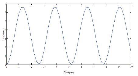
Figure 4. Step Response of Magnetic levitation system with proportional controller
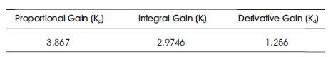
Table 2. Parameters of PID Controller
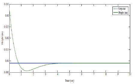
Figure 5. Closed loop response
Although PID parameters obtained using Zeigler Nicholas closed loop method gives a settling response, it is not a satisfactory response. Hence we need to tune the parameters of the PID controller using a Optimization method. Here we used the genetic algorithm technique in order to fine tune the PID parameters, so as the ball gets settled quickly. The flowchart as shown in Figure 6 explains the function of genetic algorithm [8].
The desired PID parameters around a operating point is chosen as the initial population. The population of next generation is determined by n random experiments. The resultant parent chromosomes which are having small error that means a best fitness function among other chromosomes are selected and forced to do crossover and mutation. The function of the crossover operator is to generate new or child' chromosomes from two parent' chromosomes by combining the information extracted from the parents. Mutation operates individually on each individual by probilistically perturbing each bit string.
The above block representation in Figure 7 shows that the PID parameters are optimized using genetic algorithm and provide a better response compared to the PID whose parameters are obtained using Zeigler Nicholas closed loop method. The parameters optimized using Genetic Algorithm are tabulated in Table 3.
The closed loop response obtained, when using Optimized PID is shown in Figure 8.
From the above response, we infer that the steel ball is initially at the position of 33.5mm corresponding to the voltage of 2 V. After applying the control signal to the maglev setup, the steel ball gets settled smoothly at the desired position of 9mm with a small overshoot with in 3.5sec compared to the PID parameters which are obtained using Zeigler Nicholas closed method.
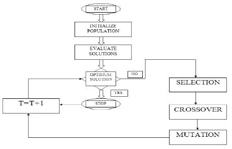
Figure 6. Function of Genetic Algorithm
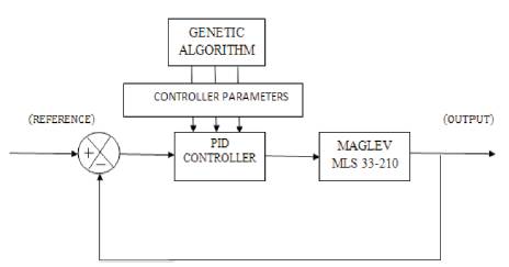
Figure 7. Block Diagram of MLS 33-210 PID-GA Implementation
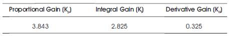
Table 3. Parameters of GA Based PID Controller
Figure 9 shows the real time implementation of PID on the maglev MLS 33-210. It has the overshoot of 38 percent and has the settling time of 4s,.but it is not satisfactory. It has to be minimized using Optimized PID.
Figure 10 shows the real time implementation of GA based PID Control on the maglev MLS 33-210. It has the overshoot of 5.55 percent and has the settling time of 3s.
Figure 11 infers that PID with GA provides a smoother response compared to the PID response. The performance analysis of PID and GA Based PID controller are analyzed quantitatively in Table 4.
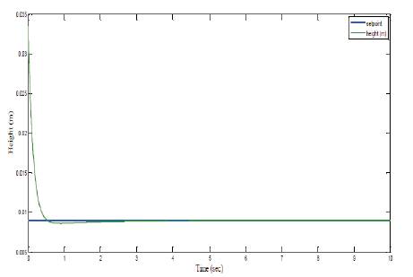
Figure 8. Closed Loop Response
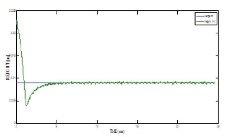
Figure 9. Closed loop response of MLS33-210
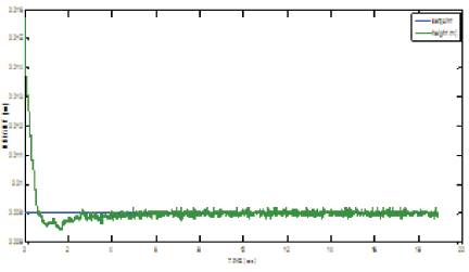
Figure 10. Closed loop response of MLS33-210 (PID-GA)
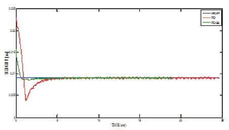
Figure 11. Performance comparison of PID AND PID-GA controllers on MLS33-210
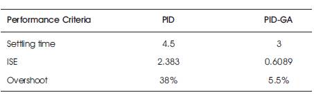
Table 4. Performance Analysis
The MLS33-210 magnetic levitation system is studied and the mathematical model of the system is developed. Conventional PID controller is developed for achieving the ball position in desired level. The closed loop response of the mathematical models, using proposed PID controller in Mat lab/Simulink is presented. GA based PID controller is implemented. The real time position control is carried out using PID controller and GA based PID controller and the responses are discussed. After analyzing the performance criteria, it is inferred that GA based PID control provides a high precision control over the Magnetic levitation system.