Figure 1. Classification of Induction State Variables Calculation Methods [3]. [3].
The basic idea is to design a fuzzy logic hysteresis comparator-based direct torque control scheme of an induction motor under varying dynamic conditions[1]. The major problem that is usually associated with DTC drive is the high torque ripple. To overcome this problem a torque hysteresis band with variable amplitude is proposed based on fuzzy logic[4]. The fuzzy logic controller is used to adjust the bandwidth of the torque hysteresis controller in order to reduce the torque and flux ripples and, to improve motor dynamic response[3],[4]. Based on the slopes of motor-estimated torque and stator current, an FLC is designed to select the optimum bandwidth of the torque hysteresis controller. In order to test the performance of the proposed FLC-based DTC scheme for IM drive, a complete simulation model is developed using MATLAB/Simulink.
During the last decade, a lot of modifications in classic Direct Torque Control scheme have been made. The objective of these modifications were to improve the start up of the motor, the operation in overload conditions and low speed region. The modifications also aimed to reduce the torque and current ripple[2], the noise level and to avoid the variable switching frequency by using switching methods with constant switching frequency.
The basic disadvantages of DTC scheme using hysteresis controllers are the variable switching frequency, the current and torque ripple[5]. The movement of stator flux vector during the changes of cyclic sectors is responsible for creating notable edge oscillations of electromagnetic torque. Another great issue is the implementation of hysteresis controllers which requires a high sampling frequency. When an hysteresis controller is implemented using a Digital Signal Processor (DSP) its operation is quite different to the analogue one.
In the analogue operation the value of the electromagnetic torque and the magnitude of the stator flux are limited in the exact desirable hysteresis band. That means, the inverter can change state each time the torque or the flux magnitude are throwing the specified limits. On the other way, the digital implementation uses specific sample time on which the magnitudes of torque and flux are checked to be in the desirable limits [7]. That means, very often, torque and flux can be out of the desirable limits until the next sampling period. For this reason, an undesirable torque and flux ripple is occurred.
In the DTC scheme a speed estimation and a torque control are applied using fuzzy logic. An improvement of DTC with a parallel control FOC is observed[8].. The use of the rotor flux magnitude instead of the stator flux magnitude, improves the overload ability of the motor. This control is sensitive to the machine's parameters during transient operations. Also, the DTC-SVM can be applied using closed loop torque control, for minimization of torque ripple. In this case estimation of stator and rotor flux is required[6]-[8].
Therefore, all the parameters of the induction motor must be known. A new method was developed that allows sensorless field-oriented control of machines with multiple non-separable or single saliencies without the introduction of an additional sensor. In this paper, the closed loop torque control method is applied which improves the torque response during dynamic and steady state performance. A lot of papers[4],[5],[6],[7] for the speed control of electrical drives, which uses different strategies based on artificial intelligence like neural network and fuzzy logic controller, have been presented. For the fuzzy PI speed controller its robustness and disturbance rejection ability is demonstrated. This paper[1] is further extended through a further improvement of the system control by controlling the magnitudes of torque and flux using closed loop control. The simulation results were validated by experimental results.
The advantages of Direct Torque Control (DTC) over its competitor Field-Oriented Control (FOC) are well known. The DTC uses flux and torque as primary control variables which are directly obtained from the motor itself. The PWM stage takes almost ten times longer processing time than the DTC to respond to the actual change. Therefore, there is no need for a separate voltage and frequency controllable PWM.
The major problem in an DTC-based motor drive is the presence of ripples in the motor-developed torque and stator flux and the switching frequency changes continuosly. The problem goes interesting, since the effective measures are adopted such as Space Vector Modulation(SVM) technique[3] which have been used to calculate the performance of open loop voltage vector modulation strategy. Hence DTC transient performance and robustness are preserved. Also FLC, an artificial intelligence-based controller is used to minimize the torque and flux ripples for transient-state conditions [5], [6]. PIcontroller is used in steady-state condition.
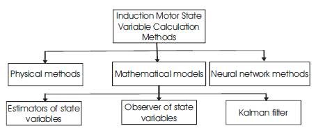
The vector control methods of induction motor require feedback signals. This is an information about flux, torque and mechanical speed in drives operated without mechanical sensor (sensorless operation mode). There are many different method to obtain these state variables of induction motor [3].
Basic methods can be divided into three main group:
Physical methods - based on nonlinear construction of IM
Mathematical models - used mathematical description of IM and control theory,
Neural network methods - based on the artificial intelligence techniques.
The general classification of the state variables calculation methods is presented in Figure 1.
Figure 1. Classification of Induction State Variables Calculation Methods [3]. [3].
The principle of the Field Oriented Control (FOC) is based on an analogy to the separately excited dc motor. In this motor flux and torque can be controlled independently [8]. The control algorithm can be implemented using simple regulators, e.g. PI-regulators.
In Induction motor independent control of flux and torque is possible in the case of coordinate system which is connected with rotor flux vector. A coordinate system d-q is rotating with the angular speed equal to rotor flux vector angular speed, Ω =Ωsr, which is defined as follows,

Therefore, current components Isα , Isβ must be transformed to the rotating system d-q .Similarly, the reference stator voltage vector components Uscα , Uscβ , must be transformed from the system d-q to α-β as in Figure 2 [3]. These transformations require a rotor flux angle γsr . Depending on calculations of this angle, two different kind of field oriented control methods maybe considered. Those are Direct Field Oriented Control (DFOC) and Indirect Field Oriented Control (IFOC) methods.
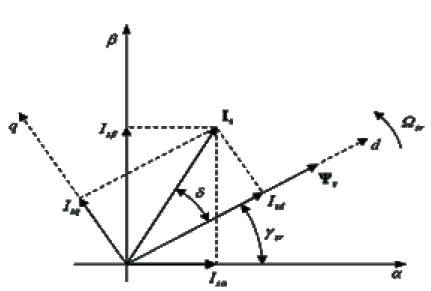
Figure 2. Vector diagram of induction motor in Stationary α-β and rotating d-q coordinates [5].
In vector control methods this part of algorithm is especially important. Estimation algorithm uses as input signals values, which are simple to measure. There are current and voltage signals. Obviously new methods aim at reducing number of sensors for more reliable operation and lower price of a drive. The motor flux is the main component to calculate torque and speed. Therefore, accuracy of the estimation flux is very important. Flux estimation is a significant task in implementation of high-performance motor drives.
The advanced state variables calculation algorithm is characterized by [9]:
Accuracy in steady and dynamic states,
Robustness for motor parameters variation,
Minimal number of sensor,
Operation in whole speed range,
Low calculation demand.
All estimation algorithms are based on the motor parameters. These parameters change in time work of the drive. For instance, with change in the temperature. Therefore, estimation algorithm have to be less sensitive to the parameters variations.
DTC principle is widely employed for induction motor drives with fast dynamics. The main notion of the conventional DTC is the rate of change of torque is proportional to the instantaneous slip between the stator flux and rotor flux under constant stator flux linkage[9], [10]. DTC has been widely recognized for its fast and robust torque and flux control. The rotor flux linkage changes is slowly compared to the stator flux linkage, as the rotor time constant of a standard squirrel-cage induction machine is very large. However, the rotor flux is almost unchanged during a short transient. Thus rapid changes of the electromagnetic torque can be produced by rotating the stator flux in the required direction, as directed by the torque command [12]. On the other hand the stator flux can instantaneously be accelerated or decelerated by applying proper stator.
Thus, the simultaneous and decoupled control of torque and flux is achieved by direct adjustment of the stator voltage in response to the torque and flux errors. The DTC regularly applies the appropriate voltage vector in order to maintain the torque and stator flux within two hysteresis bands which results in bangbang behavior and produces variation in witching frequency and significant ripple in flux, torque and current[6].
The schematic of the basic functional blocks used to implement the proposed DTFC of induction motor drive is shown in Figure 3. A voltage source inverter supplies the motor and instantaneous values of the stator flux and torque are calculated from stator variable by using a closed loop estimator[5]. Stator flux and torque can be controlled directly and independently by properly selecting the inverter switching.
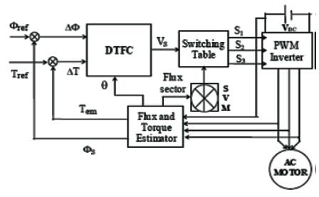
Figure 3. Direct Torque Fuzzy Control scheme for AC motor drives [5].
The conventional IM DTC method has an Artificial Neural Network (ANN) speed estimator, a Fuzzy Controller (FC) for the inverter switching frequency regulation that adjusts the hysteresis band amplitudes in the flux and torque control loops, a variable switching sector block (S-V) for shifting the sectors in the DTC method; the block (A) fixes the value of angle that rotates the sectors in the complex plane, a fuzzy system to tune the proportional and integral gains of the PI speed controller, and an ANN that estimates the stator resistance[13].
The Space Vector Modulation (SVM) technique is used to approximate the voltage vector by employing the one out of eight possible combinations of vectors generated by 3- Φ phase voltage source inverter for AC motor drives[3]. In a 3-Φ, voltage source inverter, the switching commands of each limb are complementary. So, for each limb, logic state Si (where i=1 to 3) is ON (“1”) or OFF (“0”) can be defined. As there are three independent limbs, there will be eight different logic states, which provide eight different voltages obtained applying the vector transformation described as[3]:
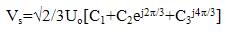
Eight switching combinations can be taken according to the above relationship: two zero voltage vectors and six non-zero voltage vectors as in Figure 4.
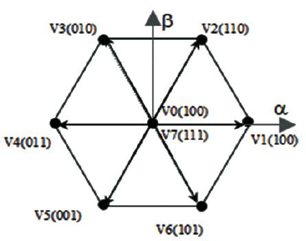
Figure 4. Partition of the αβ plane into 6 angular sectors
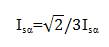
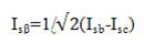
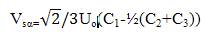
The components of the current (Isα , Isβ ), and stator voltage (Vsα, Vsβ) are obtained by the application of the transformation given by[5],[6],
The components of the stator flux (ϕsα , ϕsβ ) is given by,
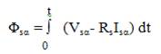
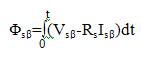
The stator flux linkage phase is given by,
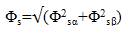
The electromagnetic couple is obtained starting from the estimated sizes of flux (Φsα, Φsβ) and calculated sizes of the current, Isα, Isβ),
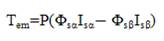
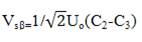
The stator resistance Rs can be assumed constant during a large number of converter switching periods Te. The voltage vector applied to the induction motor remains also constant for one period Te. Therefore, resolving first equation of system leads to,
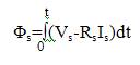
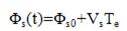
Φs0 stands for the initial stator flux condition. This equation shows that when the term RsIs can be neglected, (in high speed operating condition for example), when the extremity of stator flux vector is Vs. Furthermore, the instantaneous flux speed is only governed by voltage vector amplitude.
Therefore, by adequate voltage vector selection we can increase or decrease the stator flux amplitude and phase to obtain the required performances. The deviation obtained at the end of the switching period Te can be approached by the first order Taylor Series[5]-[4]. The radial component (component of flux) of the vector of tension acts on the amplitude of the vector flux and its tangential component (component of the torque) on the position of the vector flux. By choosing a suitable sequence of the vectors of tension, one can force the end of the vector flux to follow a desired trajectory. To function with a module of practically constant flux ϕs , it is enough to choose an almost circular trajectory for the end of the vector flux. That is not possible if the period of control is very weak for you in front of the period of rotation of flux.
When flux is in zone I, the vectors Vi+1 or Vi-1 are selected to increase the amplitude of flux, and Vi+2 or Vi-2 to decrease it. The choice of the vector tension depends on the sign of the error of flux, independently of its amplitude. This explains why the exit of the corrector of flux can be a Boolean variable[4],[13]. One adds a band of hysteresis around zero to avoid useless commutations when the error of flux is very small.
Indeed, with this type of corrector in spite of his simplicity, one can easily control and maintain the end of the vector flux, in a circular ring. The switching table proposed by Takahashi, is given in Table 1. The use of the six voltagevector switching scheme implies that stator flux linkage is always kept in motion, making it go forward and backward in order to regulate the torque loop well. To control torque at low speed without this dependency with the motion of the rotor, quick change of d can be forced by not applying the zero voltage vectors and by applying voltage vectors which move the stator flux linkage vector relative to the flux linkage due to the rotor as quickly as possible. At high speed, the rotor may move sufficiently quickly to produce the required change in d and hence torque, as required.
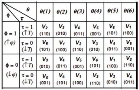
Table 1. The Switching table for DTC basis [6].
The advantages of Direct Torque Control (DTC) over its competitor Field-Oriented Control (FOC) are well known. The DTC utilizes hysteresis band controllers for both stator flux-linkage and motor-developed torque controls. Unlike FOC, the DTC scheme does not need any coordinate transformation, Pulse Width Modulation (PWM), and current regulators[11]. The PWM stage takes almost ten times longer processing time than the DTC to respond to the actual change. The DTC uses flux and torque as primary control variables which are directly obtained from the motor itself.
Therefore, there is no need for a separate voltage and frequency controllable PWM. This characteristic makes the DTC simpler and much faster in responding to load changes as compared to the FOC. The major problem in a DTC-based motor drive is the presence of ripples in the motor-developed torque and stator flux. Generally, there are two main techniques to reduce the torque ripples[14]. The first one is to use a multilevel inverter which will provide the more precise control of motor torque and flux.
However, the cost and complexity of the controller increase proportionally. The other method is space vector modulation. Its drawback is that the switching frequency still changes continuously. Advantages of intelligent controllers such as fuzzy logic, neural network, neuro-fuzzy, etc., are well known as their designs do not depend on accurate mathematical model of the system and they can handle nonlinearity of arbitrary complexity[4]. Among different intelligent algorithms, fuzzy logic is the simplest, and it does not require intensive mathematical analysis.
Artificial intelligence-based controllers have been used by the researchers for the minimization of torque and stator flux ripples in DTC scheme-based Induction Motor (IM) drives. A Proportional Integral (PI) and Fuzzy Logic Controller (FLC)-based hybrid speed controller has been used [12]. It uses an FLC in the transient state and a PI controller in the steady state. The switching mechanism between the two controllers is based on the speed error between the reference and actual speed of the motor. The threshold of the switching limit for the two controllers is based on the sampling frequency and the type of FLC used. This feature makes the switching transition complicated.
Moreover, the PI controller is used in the steady state which, inherently, is motor parameter and disturbance dependent. The FLC used by every author has two input variables. Each variable has seven membership functions, and the controller uses 49 fuzzy rules to evaluate the output[1],[5],[6]. Due to high computational burden of the controller, each work is not embodied by the real-time implementation and is only supported by the simulation results. The authors have replaced the classical DTC switching table by an artificial intelligence-based switching mechanism to produce the inverter input voltage vector. The implementation of these schemes is almost impossible in real time due to high computational burden of the selected neural and fuzzy network.
A Mamdani-type FLC is developed to adapt the torque hysteresis band in order to reduce the ripples in the motordeveloped torque. In conventional DTC technique, the amplitude of the torque hysteresis band is fixed[4]. However, in this proposed scheme, the FLC controls the upper and lower limits of the torque hysteresis band on the basis of its feedback inputs. The fuzzy systems are universal function approximators.
The FLC is used as a nonlinear function approximator producing a suitable change in the bandwidth of the torque hysteresis controller in order to keep the torque ripples minimum. There are five membership functions for one input (dTe) and three membership functions for another input (dIs). Automatically, there will be fifteen rules. For the inputs, we use triangular/trapezoidal membership functions in order to reduce the computational burden[14].
However, Gaussian membership functions are chosen for the output so that the hysteresis bandwidth will be changed smoothly. The nonlinear mapping from the input to the output of FLC is done by trial and error and experience basis. First, the membership functions and fuzzy rules were developed in simulation program by trial-and-error method so that the motor can follow the command speed with optimum level of torque ripples. Then, these fuzzy rules are applied in real-time program. From Faraday's electromagnetic theory for coil wound on unsaturated magnetic material (linear range of magnetizing curve), the stator flux linkage is proportional to the stator current. Therefore, the motor-estimated torque variation(dTe) and stator current variation (dIs) over a sampling period are chosen as inputs to the FLC which can be defined by the following equations[1]:
where Te[n] and Te[n − 1] present the present and previous samples of motor-estimated torque, respectively. The motor mechanical equation, neglecting the friction coefficient, can be written as,
Combining equations leads to the conclusion that reducing the motor torque ripples directly reduces the motor speed ripples as well. The output of the FLC is the change in torque hysteresis bandwidth “ΔHBT”. The updated upper and lower bandwidths of the torque hysteresis controller are obtained as,
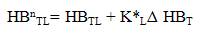
where HBTU and HBTL are the base fixed upper and lower bandwidths of the torque hysteresis comparator. KU and KL are the scaling factors. The FLC is designed on the basis of observation of simulation results of the conventional DTC based drive[13]. The amount of positive torque ripple varies inversely with the load and speed. The reverse is the case for the negative torque slope. while the membership functions of the input and output variables of FLC are shown in Figure 5.
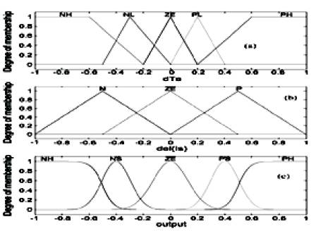
Figure 5. Membership functions for input/output variables of FLC [4].
In the FLC-DTC scheme, the hysteresis bands creating the torque and flux control logic signals are replaced by a Fuzzy Rule based controller as shown in Figure 5. The switching look up table is realized using Fuzzy rules. The fuzzy controller proposed here has been designed so as to use three fuzzy state variables as inputs and three control outputs to achieve the switching pattern for the VSI. The three fuzzy state variables inputs are flux error, torque error and the angular position of the stator flux[13],[14]. The absolute flux is compared with the rated flux of the threephase induction motor (0.5606 Wb) to obtain the flux error. The six voltage vectors (differential stator flux) for any specific positioned stator flux indicate either increase or decrease of the stator flux for flux control. Thus, flux errors are identified by three state variables chosen as membership functions. The membership function N intends to decrease the flux, P intends to increase it and Z denotes no change in stator flux.
The torque error is calculated by comparing the calculated electromagnetic torque with the desired command torque. Considering the stator flux to dwell in the first 600 in the air gap space and assuming the torque and flux errors to be positive, the demanding voltage phasor will tend to increase the torque [15]. The voltage demand can be satisfied with voltage phasor in sector I or VI. If the flux is in first 300 of sector I, then any of the above voltage vectors can meet the purpose.
Fuzzy logic, which is the logic on which fuzzy control is based is much closer in spirit to human thinking and natural language than the traditional logic system. Basically, it provides an effective means of capturing the approximate, inexact nature of the real world[12]. The essential part of the fuzzy logic controller is a set of linguistic control rules related by the dual concepts of fuzzy implication and the compositional rule of inference. A simpler practically feasible FLC is designed that selects the appropriate bandwidth for the torque hysteresis controller to optimize the ripple level in the developed torque and, hence, to improve the motor speed response. The FLC is used as a nonlinear function approximator producing a suitable change in the bandwidth of the torque hysteresis controller in order to keep the torque ripples minimum. The input variables in a fuzzy control system are in general mapped by sets of membership functions similar to this, known as "fuzzy sets". The process of converting a crisp input value to a fuzzy value is called "fuzzification"[9]. Figure 6 shows the Fuzzy Direct Torque Controlled IM.
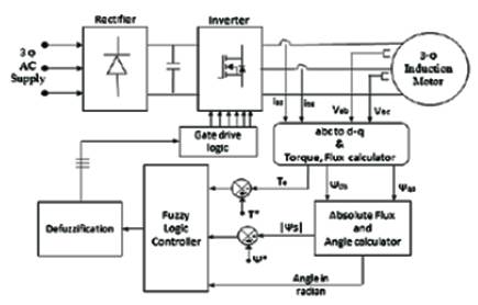
Figure 6. Fuzzy Direct Torque Controlled IM[14].
A control system may also have various types of switch, or "ON-OFF", inputs along with its analog inputs, and such switch inputs of course will always have a truth value equal to either 1 or 0, but the scheme can deal with them as simplified fuzzy functions that happen to be either one value or another. The fuzzy logic has been proved powerful and able to resolve many problems. A fuzzy controller seems to be a reasonable choice to evaluate the amplitude of torque hysteresis band according to the torque ripple level. In this paper, the amplitude of torque hysteresis band is not prefixed but it is determined by a fuzzy controller[9]-[13]. Based on the analysis, two inputs are chosen, speed error variation and stator current variation. Figure 7 shows Simulation diagram of the IM drive system based on DTC with Fuzzy Logic Controller.
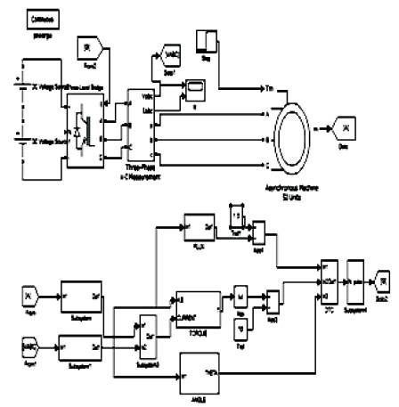
Figure 7. Simulation diagram of the IM drive system based on DTC with Fuzzy Logic Controller
The fuzzy controller design is based on intuition and simulation. For different values of motor speed and current, the values reducing torque and flux ripple were found. These values composed a training set which is used to extract the table rule. The shapes of membership functions are refined trough simulation and testing. The membership functions of input and output variables[15]. The rules were formulated using analysis data obtained from the simulation of the system using different values of torque hysteresis band. If the amplitude is set too small, the overshoot may touch the upper band which will cause a reverse voltage vector to be selected. This voltage will reduce rapidly the torque causing undershoot in torque response consequently the torque ripple will remain high.
The simulations of the DTC induction motor drive were carried out using the Matlab/Simulink simulation package. We get speed fuzzy DTC control of the induction machine shows the Vab, Iab, Speed, Torque characteristics with Conventional DTC and Fuzzy DTC. The torque ripple is significantly reduced when fuzzy controller is in use. The fuzzy controller provides the desired amplitude according to the torque ripple level and operating condition. It is seen that the steady state performance of the DTC-with fuzzy controller is much better than of the DTC-without fuzzy controller. For dynamic performance, the modified DTC is almost as good as the conventional DTC.
Figure 8 shows the voltage, current, steady-state speed and torque responses. The conventional DTC scheme has approximate average speed ripples of 0.02 rad/s with some very big abrupt peaks. By using the proposed DTC scheme, the speed response is very smooth, and there are almost negligible ripples.
Also the waveform shows, the simulation responses for a step change in command speed from 100 to 150 rad/s at t = 0.15 s while the motor is running at a 40% rated load (0.5 Nm). Also, it represents the corresponding torque response of the proposed DTC schemes. It can be compared that, in the steady state, the torque ripple in the conventional scheme is approximately 0.5 Nm while, in the proposed scheme, it is only 0.2 Nm, which proves the superiority of the proposed DTC scheme over the conventional one.
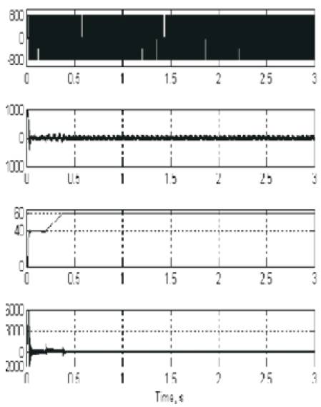
Figure 8. Vab, Iab, Speed, Torque Characteristics with Fuzzy DTC
Thus, a speed DTC drive with fuzzy controller determinates the desired amplitude of torque hysteresis band. Also the proposed scheme results in improved stator flux and torque responses under steady state condition. The main advantage is the improvement of torque and flux ripple characteristics at low speed region, this provides an opportunity for motor operation under minimum switching loss and noise. This controller determinates the desired amplitude of torque hysteresis band.
The direct torque controller implemented used a simplified technique for handling transient conditions. If there was insufficient voltage available to drive the stator flux and torque to the new reference values in a single switching cycle, then a single voltage vector was selected that would drive both the torque and flux in the required direction. This technique can result in loss of precise control over the torque and flux for the duration of the transient. These were a calculation intensive approach that maintains full control over of torque and flux during transient conditions, and a simplified technique that provides good control over torque but sacrifices flux control performance. Using one of these techniques would enable improved control over torque and flux during transient condition.