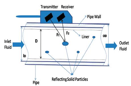
Figure 1. Doppler Method
This paper explains the different Methods of Placement and Installation of Ultrasonic Flow Measuring Instrument on the Pipe of different configuration to extend the linearity range of measurement up to maximum of the input range. Accurate flow measurement is an essential requirement both from qualitative and economic points of view. Among the non contact type of flow measurement, Ultrasonic Flow Measurement (UFM) is widely used to measure flow, because of its advantage like high resolution and less interference of noise on output. However, non linear characteristics of Ultrasonic flow meters have restricted its use [1-2]. But the different arrangement and Installation method helps us to understand, how to linearise the overall system to maximise its full scale range and to make it adaptive to variations in pipe diameter, liquid density, and liquid temperature [3-4]. A flowmeter installed in such a pipeline should indicate the volumetric flowrate correctly and independently of the flow profile. The ultrasonic flowmeter integrates, or averages, the velocity along its measuring paths [8-11]. Clamp-on transducers eliminate in-line installation, allowing one meter to be used at many locations. For easy installation, no moving parts and no contact between transducer and Fluid is required. Exterior installation eliminates pressure losses and prevents leaking that can be associated with in-line meter installations [15].
Flow measurement is the quantification of bulk fluid movement. Flow can be measured in a variety of ways, may be by contact type or non-contact type of sensor. Positive-displacement flow meters accumulate a fixed volume of fluid and then count the number of times the volume is filled to measure flow. Other indirect flow measurement methods rely on forces produced by the flowing stream as it overcomes a known constriction [7-9]. Flow may be measured by measuring the velocity of fluid over a known area.
Ultrasonic flow meters have gained a lot of attention over the past years, primarily because of their ability for measuring custody transfer of natural gas. They are replacing differential pressure and turbine flow meters in many natural gas applications. Ultrasonic Flowmeters are also widely used to measure liquid flow. This is not limited to clean liquids either [5-6]. A special type of Ultrasonic Flowmeter can accurately measure the flow of slurries and liquids with many impurities.
Ultrasonic flow meters are one of the most interesting types of meters used to measure flow in pipes. There are two types of Ultrasonic techniques available in the Market used for the measurement of the Flow in pipes which are follows.
This method needs reflectors in the process. Due to malfunctioning, and incorrect application, there is feeling of uncertainty, in ultrasonic flow measurement. Instead of tracking the time it takes to cross the other side, it relies on having the signal deflected by particles in the flowstream. These particles are traveling at the same speed of the flow [10]. Therefore, as the signal passes through the stream, its frequency shifts in proportion to the mean velocity of the fluid. A receiver detects the reflected signal and measures its frequency as shown in Figure 1. The meter calculates flow by comparing the generated and detected frequencies.
Figure 1. Doppler Method
Doppler method relies on reflectors in the flowing liquid. To obtain reliable measurements, therefore, attention must be given to the lower limits for concentrations and sizes of solids or bubbles [12-13]. The flow must also be rapid enough to keep these materials in suspension.
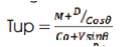
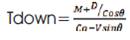
The most common used, transit time method; have both a sending and a receiving transducer. Figure 2 shows the arrangement of one such Ultrasonic Flowmeter. Both sending and receiving transducers are mounted on either side of the flow meter, or the pipe wall. The sending transducer sends an ultrasonic signal at an angle from one side of the pipe which is received by the receiving transducer. The flow meter measures the time that the ultrasonic signal takes to travel across the pipe in forward and reverse direction. When the signal travels along the direction of the flow, it travels more quickly compared to the condition of no flow. On the other hand, when the signal travels against the direction of flow, it slows down. The difference between the “transit times” of the two signals is proportional to flow rate[5, 10-13].
To overcome the restriction faced due to nonlinear response characteristics of the ultrasonic flow meter, several techniques have been suggested [19-20]. But some of these are tedious and time consuming. Further, the process of calibration needs to be repeated or calibration circuit needs to be replaced/ tuned every time there is a change in pipe diameter or liquid density. The problem of nonlinear response characteristics of an Ultrasonic Flowmeter further aggravates when there is a change in liquid temperature, since the output of an Ultrasonic Flowmeter is dependent on temperature also.
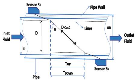
Figure 2. Transit-Time Method
From Figure 2, we have
Frequency, FIN = 1/ΔT
Where
M – No of times ultrasonic signal travels in forward/ backward direction
Co – Velocity of ultrasonic signal in static fluid
D – Pipe diameter
V – Velocity of fluid
The velocity of ultrasonic signal depends on [13] density of liquid as shown in Figure 3

With k – bulk modulus and
ρ – Density of liquid
Effect of temperature on density [14-15] can be given by
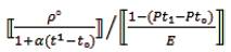
Where:-
ρ1 – specific density of liquid at temperature t1
ρ0 - specific density of liquid at temperature t0
Pt1 – pressure at temperature t1
Pt0 – pressure at temperature t0
E– Modulus of elasticity of the liquid
α – temperature coefficient of liquid
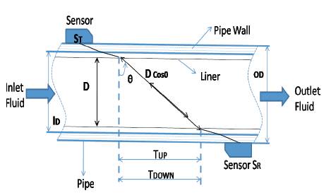
Figure 3. Direct Mode or Z-Method
Meters are chosen for their application by their performance characteristics. The Ultrasonic Flowmeter is a high accuracy (custody transfer quality), wide flow range meter capable of high accuracy at high or low flow rates. Ultrasonic Flowmeters are large capacity meters for their diametric size. They are calibrated meters and commonly replace multiple parallel orifice meters with only one Ultrasonic Flowmeter. They are more tolerant to tube wall build-up than most meters. They are full-bore with no restriction. Flowmeters measure very low flow rates or rates as fast as you would operate a line without causing component erosion [14]. The meter's wet-gas performance is excellent compared to conventional high accuracy metering technologies. Ultrasonic meters operate well at high pressures. They are in operation in gas injection applications up to 10,000 PSI. The characteristics alone offer a wide choice of applications; however, it is interesting that only a few meter tube design configurations are necessary to accomplish the entire range of applications [16-18]. There are numerous site configurations possible. Designers should plan site tie-ins carefully.
There are three methods by which Ultrasonic Flow measuring instrument can be installed in the pipe according to the condition of the Fluids, which are as follows.
1. Direct Mode (Z-Method) Installation
In this Direct Mode or Z-Method of Installation, Ultrasonic flow measuring Sensor or Transreceiver can be installed opposite to each other as shown in Figure 3.
2. Reflecting Mode Installation or V-Method
In this Reflecting mode or V-Method of Installation, Ultrasonic flow measuring Sensor or Transreceiver can be installed in the Same Line at predefined distance to each other as shown in Figure 4.
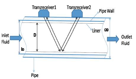
Figure 4. Reflecting Mode or V-Method
Ultrasonic sound wave reflects from wall of the Pipe and makes V-shape. The graph shown in Figure 5, gives the difference between ultrasonic waves along the flow of fluid (T1-T2) and opposite to the flow of fluid (T2-T1).
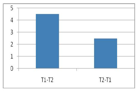
Figure 5. Graph between T1-T2 and T2-T1.
W-Methods
In this W-Method of Installation, Ultrasonic flow measuring Sensor or Transreceiver can be installed in the Same Line at predefined distance to each other, which is slightly more than V-Method as shown in Figure 6, because to extend the linearity range of measurement up to maximum of the input range and make W- shape.
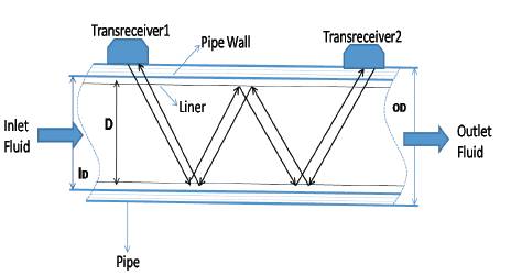
Figure 6. W-Method of Installation.
For liquid flow measurements on pipelines DN 15 to 5000,
Such clamp-on devices are available in two versions:
The following points need to be borne in mind when selecting the mounting location:-
Parameters such as:-
Affect the beam's angle of incidence as shown in Figure 7 the path length of the sound waves, and hence the transit times and the necessary sensor distance is achieved. For that reason, the signal converter polls these parameters in dialog, computes the sensor distance for setting the two sensor assemblies, and includes this data in the flow computation. Measuring-point data can be stored and used for subsequent measurements. The portable signal converter has an internal data logger to allow recording of the flowrate. This data can then be transmitted via an interface to a PC at a later date. For continuous process flow measurements with high accuracy requirements, absolutely no maintenance, and the greatest possible independence from the Reynolds number and other process conditions this is used.
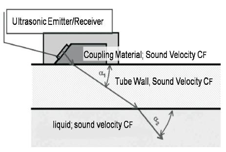
Figure 7. Sonic coupling in clamp-on ultrasonic flowmeters
A laminar and a turbulent flow profile at the same volumetric flow rate.
Some petrochemical products have very high viscosities, so laminar flow can also occur in large-diameter pipelines. If a low-viscosity product is involved, the flow can in turn be turbulent. A flowmeter installed in such a pipeline should indicate the volumetric flowrate correctly and independently of the flow profile. The ultrasonic flowmeter integrates, or averages, the velocity along its measuring paths. In laminar flow conditions, and with only one ultrasonic beam passing through the tube centerline, it averages by way of the peak of the parabolic flow profile. In turbulent flow conditions, it averages by way of the much flatter profile. Measurement results are inevitably different. For accurate flow measurement independent of the Reynolds number, ultrasonic flowmeters are available with a number of measuring channels adapted to the task in hand. Figure 8 shows the Typical Piping and Meter Configuration.
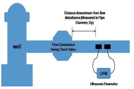
Figure 8. Typical Piping & Meter Configuration
Versions of ultrasonic flowmeters are available today in which the measuring beam is reflected from the tube wall several times in order to reduce the effect of the flow profile and to extend the linearity range of measurement up to maximum of the input range. This method does have its advantages:-
However, this design also involves risks:-
The proposed method of placement and installation of Ultrasonic Flow Measuring Instrument has gained intelligence in addition to increase in the linearity range. The output is somehow made adaptive to variations in pipe diameter and liquid density. Thus, if the liquid is changed by another liquid of different density, and/or the pipe is replaced by another pipe of different diameter, and/or liquid temperature is changed then the calibration process need not be repeated. These different methods of Installation of Ultrasonic Flow Measuring Instrument on the Pipe of different Configuration, extend the linearity range of measurement up to maximum of the input range. Clampon transducers eliminate in-line installation, allowing one meter to be used at many locations. For Easy installation, no moving parts and no contact between transducer and Fluid is required. Exterior installation eliminates pressure losses and prevents leaking that can be associated with inline meter installations.