(1)
This paper presents the hardware design methodology of digital control systems with different control algorithms. The control system is designed using Xilinx Spartan 3E FPGA, which consists of Analog Capture Circuit, PWM signal generator and other essential modules to control the process. The National Instruments LabVIEW is chosen as the software platform to interface with the FPGA kit. The hardware has been designed to study the Static as well as Dynamic characteristics of DC Motor, with three different control algorithms such as PI,PD and PID. The Ziegler Nichols method has been employed for tuning of controller parameters and the responses of three control algorithms are compared. The novelty in the project has been the measurement of speed, which is done through the design of Timer & Counter using the software, rather then employing the Tachometer, hence reducing the cost.
At the highest level, FPGAs are reprogrammable silicon chips. Using prebuilt logic blocks and programmable routing resources, these chips can be configured to implement custom hardware functionality without ever having to pick up a breadboard or soldering iron. It is possible to develop digital computing tasks in software and compile them down to a configuration file or bit stream that contains information on how the components should be wired together. In the past, FPGA technology could be used only by engineers with a deep understanding of digital hardware design. The rise of high-level design tools, however, is changing the rules of FPGA programming, with new technologies that convert graphical block diagrams or even C code into digital hardware circuitry.
FPGA chip adoption across all industries is driven by the fact that FPGAs combine the best parts of ASICs and processorbased systems. FPGAs provide hardware-timed speed and reliability, but they do not require high volumes to justify the large upfront expense of custom ASIC design. Reprogrammable silicon also has the same flexibility of software running on a processor-based system, but it is not limited by the number of processing cores available. Unlike processors, FPGAs are truly parallel in nature, so different processing operations do not have to compete for the same resources. Each independent processing task is assigned to a dedicated section of the chip, and can function autonomously without any influence from other logic blocks.
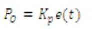
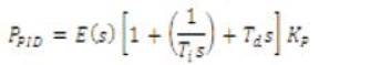
The proportional term makes a change to the output that is proportional to the current error value. The proportional response can be adjusted by multiplying the error by a constant Kp , called the proportional gain.
The proportional term is given by:
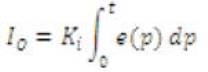
The contribution from the integral term is proportional to both the magnitude of the error and the duration of the error. The integral in a PID controller is the sum of the instantaneous error over time and gives the accumulated offset that should have been corrected previously. The accumulated error is then multiplied by the integral gain (Ki) and added to the controller output. The integral term is given by:
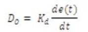
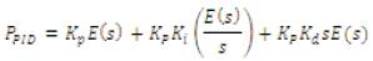
The derivative of the process error is calculated by determining the slope of the error over time and multiplying this rate of change by the derivative gain Kd . The magnitude of the contribution of the derivative term to the overall control action is termed the derivative gain, Kd . The derivative term is given by eqn (3):
To get the effective values of controller parameters, Ziegler Nichols Open loop tuning method has been chosen.
The process variable is brought to the setpoint, by manually adjusting the control variable, with the controller in manual mode. Then, the PID controller can be converted into P controller, by setting Ti=α and td=0 The value of Kp is increased from zero, till the sustained oscillations are attained by the control system. This value of proportional gain Kp called ultimate gain is measured and corresponding ultimate period Pu is noted.
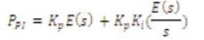
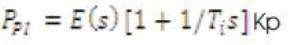
The output of Proportional plus Integral controller is given as:
The output of Proportional plus Derivative controller is given as:
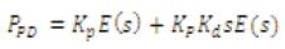
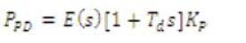
The output of Proportional plus Derivative controller is given as:
The process chosen to be controlled by different control algorithms[3]. Hence the controllers are to be tuned to get the best values for the parameters like Kp, Ki, Kd.
Considering the Dynamic characteristics of the motor, the transfer function model of the DC motor is chosen as:
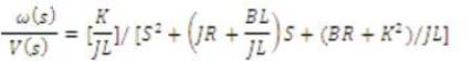
Where,
ω(s) is angular velocity in rad/sec
V(s) is applied voltage(v)
J is Rotor Inertia (9.64E-6)
R is rotor resistance (3.3Ω)
K is Torque constant (0.028N-m/A)
L is Inductance (4.64E-3 H)
B is Friction Torque Coefficient(1.8E-6 N-m-s)
Figure 1 represents the Ziegler Nichols Open loop method, where the feedback path is removed for tuning the process [3]. The standard transfer function of the DC motor system as represented by the eqn(10) is framed using the LabVIEW function as shown in Figure 2. A typical procedure has been followed to tune the PID controller, based on the natures of Proportional, Integral & Derivative terms. Here, Kc i.e; critical gain is set to 1, while Ti, Td are set to 0. This is followed by the variation in Td to make the system faster as well as to compensate the overshoot. Then Ti is modified to remove any steady state error. Thus, best values of the parameters are obtained from the Tuning process. The variations in the responses are shown in the Figures 3,4 & 5.
Figure 6 shows the block diagram of the process, which is chosen for the process control. The system comprises of various components such as Xilinx Spartan-3E FPGA, Power Transistor, 12v DC Motor, Opto-coupler.
The technique used to control the power supply to the motor is Pulse Width Modulation. The pulses with constant frequency are generated from Input/Output ports of Xilinx Spartan-3E FPGA[14]. The width of these pulses can be varied and PWM can be generated using different LabVIEW FPGA functions [8].
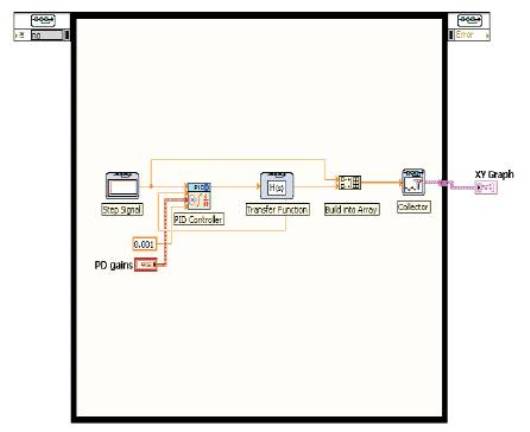
Figure 1. Code for the Tuning Process
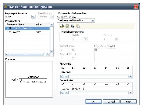
Figure 2. Configuration of the Transfer function
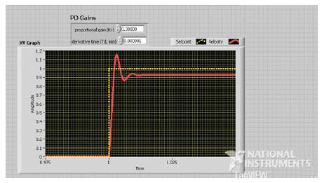
Figure 3. Step Response for the PD Controller
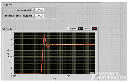
Figure 4. Step Response for the PI Controller
The generated PWM the Front Panel of LabVIEW is shown in Figure 7. This PWM is given to the base of Power Transistor, whose collector terminal is connected to the motor. Thus, the power suplly to the motor is controlled.
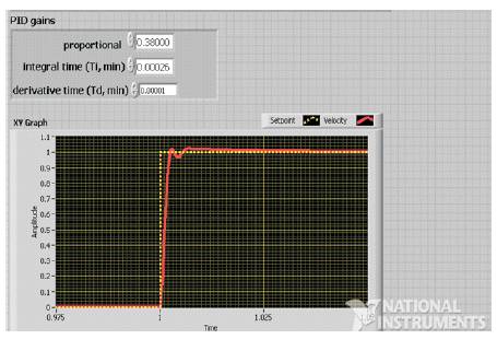
Figure 5. Step Response for the PID Controller
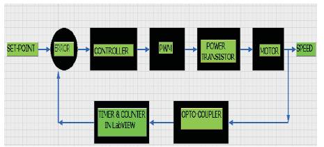
Figure 6. Block Diagram of the Process
A Timer is designed using the Timed loop in LabVIEW [8]. This Timer is used to measure certain period of time as required. The code in the Block Diagram of LabVIEW is shown in Figure 8.
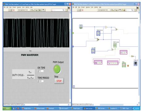
Figure 7. Generation of PWM
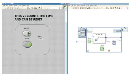
Figure 8. Design of the Timer
An Opto-coupler MOC 7811 is employed to detect the rotations of the DC motor. A counter is designed using different functions of the LabVIEW. Whenever the motor shaft passes through the Opto-coupler, a rotation is counted. Thus, in a particular period of time, number of rotations is measured using this counter. Hence, number of counts per unit time gives the speed of motor.
The speed of the motor, which is measured is given as input to the controller. The range of the output of controller is chosen as -100 to 100. This controller output is calibrated in terms of Duty cycle whose range is chosen as 0.2 to 0.8. For a particular speed of motor, there will be a controller output proportional to the difference between Set point and Process variable. Thus, corresponding to this output, there will be a value for Duty cycle, according to which, the power is supplied to the motor [7].
Figures 9- 12 show the response for different algorithms.
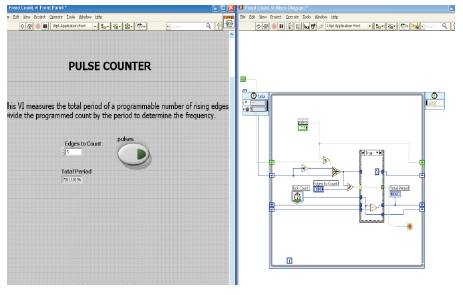
Figure 9. Design of the Counter
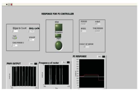
Figure 10. Response of PI controller
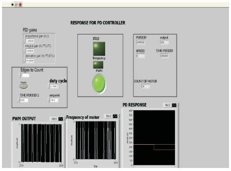
Figure 11. Response of PD controller
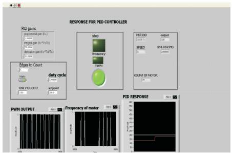
Figure 12. Response of PID controller
In this paper, digital controller has been designed using Xilinx Spartan-3E FPGA, with software platform as LabVIEW. The graphical LabVIEW FPGA code is translated to text-based VHDL code, by Xilinx ISE compiler tools. Further, this VHDL code is optimized, reduced and synthesized into hardware circuit realization of LabVIEW program. The normal clock frequency of FPGA is 51.509MHz,which means one Tick of FPGA clock is equal to 19.4 nanoseconds. The clock frequency can be increased upto 200MHz,by changing compile options. The control strategy implemented is PWM technique. The process is controlled by employing PI,PD as well as PID controllers, which are designed on FPGA using LabVIEW and the responses of three different algorithms are compared. Different control algorithms are best suitable for different kinds of processes, like PID best suits for Temperature control, PI best suits for Flow control and so on[4]. This hardware design can be utilized for process control according to the control strategy required.