[1]
This paper discusses FPGA based digital controller designed for solar tracking in satellites. The proposed controller can replace the conventional full-step controller for stepper motor in all positioning applications owing to its increased resolution capability and reduced effect of mid-frequency resonance. The concept of microstepping is discussed using PWM. The design is implemented in Xilinx ISE. Results are presented to show the substantial advantages of the proposed methodology.
The satellite is provided with solar panels for generation of power for on board applications. These panels convert solar energy into electrical energy, which is stored in the Ni-Cd batteries. The sun tracking of the two solar panels is achieved by means of high resolution hybrid stepper motors. The main objective of the drive is to maintain the solar panel normal to sun always in order to extract maximum power [1] and [2]. Stepper motors are brushless DC motor whose rotor rotates in discrete angular increments when its stator windings are energized in a programmed manner [3]. The necessity for closed loop systems arises only in applications that require variable torque output. The advantages of open loop systems are its simplicity and ease of implementation and above all they are more stable comparatively [1] . Compared with other small electromagnetic motors that can perform the same or similar functions, a control system for stepper motors has several significant advantages as stated in [4] which are, no feedback required for either position or speed control, Positional error is Non-cumulative, etc. Stepper motors are compatible with modern digital equipment. Hybrid motors have a small step length (typically1:8 deg), which can be a great advantage when high resolution angular positioning is required. The torque-producing capability for a given motor volume is greater in the hybrid than in the variable-reluctance motor, so the hybrid motor is a natural choice for applications requiring a small step length and high torque in a restricted working space [5]. One of the most unfavourable features of the stepper motors is mid-frequency resonance at low step rate [6]. However the microstepping scheme proposed in this paper reduces the phenomenon considerably.
Effort has been spent on designing the ideal hybrid stepper motor drive in various ways. Authors in [2] have designed a custom made high resolution stepper motor for solar-array drive. The prominence of closed loop commutation delay in stepper motor control is discussed in [7]. In the presence of this delay, the feedback linearization is not exact and when algorithms are employed for correction, the stability of the system reduces considerably. The fact that the open loop controllers are more stable is explored in [8] and [9]. In [10] the authors propose controller for optimal performance that uses PWM technique on a compact hardware, the method demands high switching devices and high operating frequencies. In [9] though the stepper motor is operated in open loop, the drive operates in closed loop mode using PI controller and is less stable comparatively. In present paper simplified microstepping stepper motor drive is proposed using PWM technique. The proposed work reduces the mid-frequency resonance and is highly stable being open loop system.
Although microcontrollers are suited for this applications, FPGA's hold several advantages. Nowadays, with FPGA's it is possible to build up a more flexible system because of the parallelism and the reconfigurability of the FPGA's. With a customizable system-on-chip solution, there are in addition advantages like lower costs and a small design size [10].
The content of the paper is structured as follows. In Section 1, the conceptual background of microstepping is explained. After that, an overview is given to the Microstepping using PWM based on FPGA implementation as discussed in Section 2. In Section 3 the results of simulation and implementation are discussed briefly. Finally Paper is concluded.
Stepper motors can be described as motors which rotate through small finite angular displacement (full-step, typically 1.8°) whenever an input signal, usually in the form of a voltage pulse are applied to them. Such incremental motion results in the following limitations of the stepper motor like the limited resolution, that is full step is the smallest angle through which the motor can move, this poses limitation because the stepper motor cannot position the load to an accuracy finer than full-step. Secondly the mid-frequency resonance becomes prominent at lower step rates and results in reduced torque at certain input pulse frequencies [3].
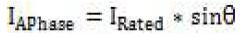
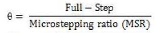
The above discussed problems can be accounted by going in for microstepping stepper motor drive. In microstepping scheme both the windings of the motor are energized simultaneously in order to make the stator magnetic flux rotate through a small angle very less than full-step. We modulate current through the two windings of the motor as shown in equation1 and equation 2 to facilitate micro stepping.

Where
The current pattern in stator windings of stepper motor is governed by look up table for winding currents of motor for microstepping ratio of 8 as listed below in Table 1. Likewise the table can be stored in ROM for various micro-stepping ratios for the operation of stepper motor. In this case the MSR chosen is 64.
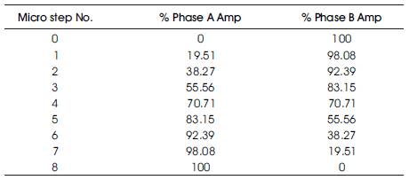
Table 1. Percentage of currents in motor windings
Figure1 shows the locus of the resultant current (IResultant) in the windings of the stepper motor. Hence, it is implied that the resultant current in the stator windings is the vector sum of the currents in the individual windings [11]. The magnitude of the resultant current can be expressed as shown in equation3 and the resultant current in its vector form can be expressed as in equation 4. IResultant being the resultant current of the motor.
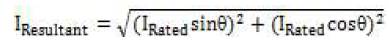
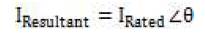
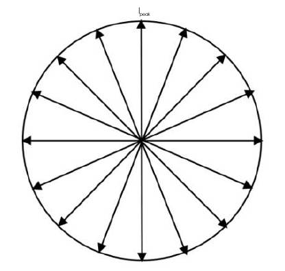
Figure 1. Locus of Resultant Current Vector in Motor winding
The overall block diagram for this scheme is as shown in Figure 2. The logic sequencer is realized using the FPGA controller which monitors the input clock and the clockwise (CW) and counter clockwise (CCW) bit and decides upon the speed of operation and the direction of rotation. A,B,C and D are the PWM drive enable signals which will force the currents in the windings of the stepper motor to flow in sine-cosine form. The motor driver block is the dual H-bridge configuration which brings about compatibility between the stepper motor and the digital controller (FPGA).
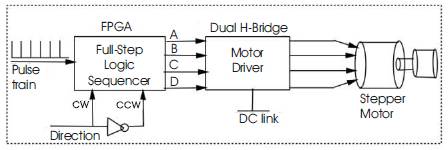
Figure 2. Block-diagram for proposed methodology
As shown in Figure 3, the PWM technique for micro-stepping requires two signals-the sawtooth carrier wave and the reference signal (Sine/Cosine) to generate the required drive enabled pulses.
The first requirement is fixed frequency base counter for PWM that is the sawtooth function as shown in Figure 3. The frequency of the sawtooth waveform decides the speed of the motor in steps/sec and the switching frequency of the external driver. The frequency of sawtooth waveform should be somewhere limited to between 10KHz and 30KHz because lower frequencies cause audible noise and high frequencies pose limitation on external driver causing electromagnetic interference. So in order to control the speed of the stepper motor the optimal range of frequency is between 10KHz and 30KHz.
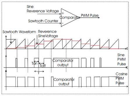
Figure 3. Concept of Generation of PWM signals
The second requirement is the reference signal in the form of sine/cosine wave. This is implemented as look up table (LUT) in Read Only Memory(ROM). Implementing in ROM saves processing time, power and chip space. This LUT can be suitably changed in order to vary the magnitude of the developed electromagnetic torque of the stepper motor.
The comparator compares the sawtooth base counter with that of sine/cosine LUT and generates the required PWM signals. In this case the sine LUT reaches its maximum value in 64 sawtooth pulses, which is the indication that the Micro-Stepping Ratio (MSR) is 64 in this case. The no of values stored in the ROM decides the MSR and can be varied as per requirement.
The Functional block diagram of the digital controller design is represented in Figure 4. It basically consists of a common synchronous clock which decides the speed of operation and hence the speed of the motor in steps/sec.
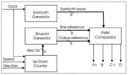
Figure 4. Functional block diagram of digital controller
The updown counter block increments whenever it encounters the rising edge of the clock for clockwise rotation and decrements for counter clock wise rotation of motor. The output count of the updown counter act as the step number to the sinusoid generation block. The sinusoid generation block is the designed ROM which contains the sinθ and cosθ values being stored as look up table for various step number input. For each step number input, the sinusoid generation block outputs new value of sinθ and cosθ as its output.
Another block diagram shown in Figure 4 is the sawtooth generation block. This block monitors the rising edge of the clock input and for every eight clock pulses, it generates one sawtooth pulse.
The PWM comparator as the name indicates compares the value of sinθ and cosθ with that of sawtooth waveform and outputs the four PWM signals which act as drive enabled signal to the external driver.
To evaluate the performance of the system, the developed algorithm was implemented in Xilinx FPGA XC50-3.This device can run at synchronous system clock rates up to 50MHz and has capacity of 50,000 gates. The tools used for simulation and implementation were Modelsim and Xililnx respectively.
Figure 5 reveals the simulation result for the clock wise direction with the MSR of 64. The drive enabled signals A, B, C and D are as shown in Figure 5. The first signal in Figure 5 is the system clock followed by the speed signal(8-bit) and the direction bit(0 for clockwise and 1 for counter clock wise). The external driver drives the currents in winding of the stepper motor in the form of sine/cosine using PWM pulses generated by digital controller and the DC link voltage of the dual H-bridge.
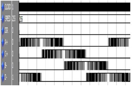
Figure 5. Drive enable signals generated using PWM in clockwise direction
Figure 6 shows the result for microstepping using PWM in counter clock wise direction. Study reveals that in order to change the direction of stepper motor it is sufficient if we reverse the current in any one winding. From Figure 6 it is evident that in this case the cosine wave in winding B is kept unchanged(C+ and D- remain unchanged) and sine wave in winding A is reversed(A+ and B- are 180deg out of phase) in reference to Figure 5 to facilitate direction reversal.
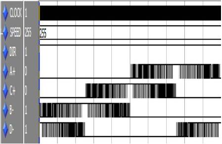
Figure 6. Drive enabled signals generated using PWM in counter clock wise direction
The synthesis report is summarized in Table 2 and Table 3. Table 2 is summary of utilized resources of FPGA and Table 3 is summary of the timing of FPGA implementation. It is evident from Table 3 that the maximum frequency of the input clock is limited to 50.97MHz.
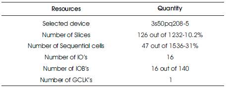
Table 2. Utilized Resources Of FPGA
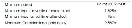
Table 3. Timing Analysis
The hardware configuration of the external driver is as shown in Figure 7. The scheme requires eight static power semiconductor devices (popularly known as dual H-Bridge configuration) to drive the sine and cosine current in windings of the stepper motor. In present day, the configuration of driver is available in form of integrated chip (L293D, L298) which reduces the hardware complexity further.
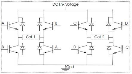
Figure 7. Schematic of Dual H-bridge inverter
The work has exhibited the results for simulation and implementation that validate the design of PWM based microstepping stepper motor drive using Xilinx ISE. Also the design accounted the issues like limited resolution and mid frequency resonance by facilitating 64 times better resolution and increased step rate. The algorithm developed to generate the PWM pulses is proved to be efficient since it utilizes lesser gates and supports operating frequency upto 50.97MHz. The sine-cosine conformation helps in maintaining constant output torque at all the positions. FPGA being far more energy efficient and flexible system, decreases processing time compared to other controllers and a single FPGA can be programmed to control multiple motors simultaneously. This feature is well exploited in solar-array drive in satellites to drive large photo voltaic array using multiple motors controlled by single FPGA.